Add device - Interface
This device supports USB and LAN.
For USB
•AC3006/3009: Both service cable can supply the device with power.
For LAN - the device IP address can be defined fix or by DHCP.
Configuration
•To display all the possible settings for the device, it has to be read out first by clicking on the button "Read".
•By clicking on the button "Write" all the changed settings will be applied to the device.
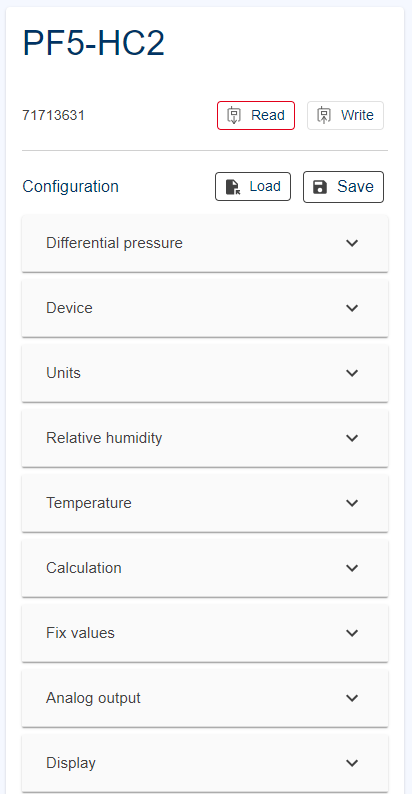
Differential pressure
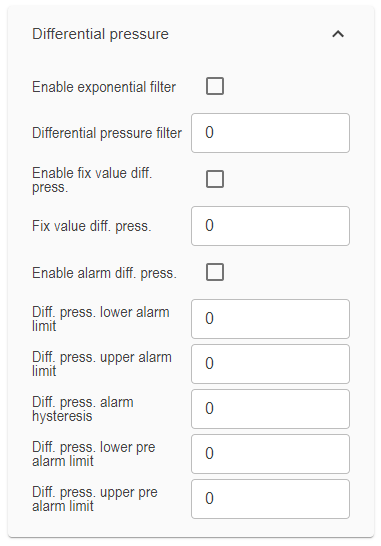
•Enable exponential filter – Enable / Disable (default). The PF4/5 has an average and an exponential filter integrated. If the checkbox is set to disabled, the average filter is used by the PF4/5. If enabled, the exponential filter is used. For a proper use of the filter function, the differential pressure filter value is to be defined - see next.
•Differential pressure filter - value between 0 - 10.
0/1 - no filter function
2 - minimum filter effect
10 - maximum filter effect
•Enable fix value diff. press. - For simulation reason, fix values can be activated.
•Fix value diff. press. - For simulation reason, fix values can be set.
•Enable alarm diff. press. - device alarms can be enabled/disabled
•Diff. press. lower/upper alarm or pre alarm limit - lower/upper pre alarm limit (for warning) or alarm limits can be defined for the device. The alarms can be used for switching a relay or colored indication on the display. The alarms are also available via modbus.
•Diff. press. alarm hysteresis - an alarm hysteresis for differential pressure can be set.
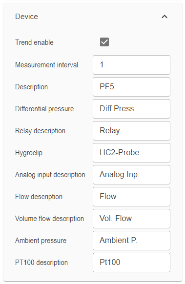
Device
•Trend enable - the trend can be enabled setting the checkbox for each measured parameter. For further details please see chapter Extras (trend duration, trend stability).
The following parameters can be named.
Units
The PF4/5 measures several parameters. The unit of each parameter can be chosen/defined.
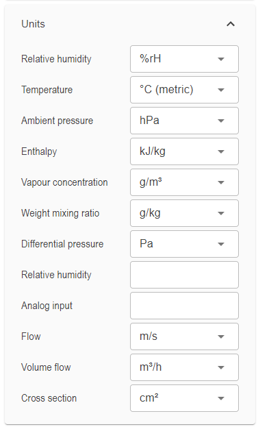
Relative Humidity
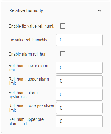
•Enable fix value rel. humi. - For simulation reason, fix values can be activated.
•Fix value rel. humi. - For simulation reason, fix values can be set.
•Enable alarm rel. humi. - device alarms can be enabled/disabled
•Rel. humi. lower/upper alarm or pre alarm limit - lower/upper pre alarm limit (for warning) or alarm limits can be defined for the device. The alarms can be used for switching a relay or colored indication on the display. The alarms are also available via modbus.
•Rel. humi. alarm hysteresis - an alarm hysteresis for differential pressure can be set. The following device settings can be named by the user.
Temperature
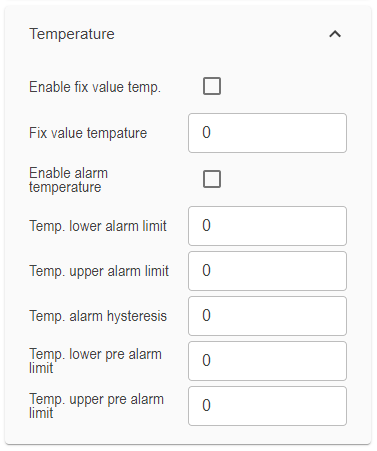
•Enable fix value temp. - For simulation reason, fix values can be activated.
•Fix value temperature - For simulation reason, fix values can be set.
•Enable alarm temperature - device alarms can be enabled/disabled
•Temp. lower/upper alarm or pre alarm limit - lower/upper pre alarm limit (for warning) or alarm limits can be defined for the device. The alarms can be used for switching a relay or colored indication on the display. The alarms are also available via modbus.
•Temp. alarm hysteresis - an alarm hysteresis for differential pressure can be set. The following device settings can be named by the user.
Calculation
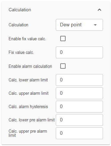
•Calculation - Chose of the psychometric measurement parameter.
•Enable fix value calc. - For simulation reason, fix values can be activated.
•Fix value calc. - For simulation reason, fix values can be set.
•Enable alarm calculation - device alarms can be enabled/disabled
•Temp. lower/upper alarm or pre alarm limit - lower/upper pre alarm limit (for warning) or alarm limits can be defined for the device. The alarms can be used for switching a relay or colored indication on the display. The alarms are also available via modbus.
•Temp. alarm hysteresis - an alarm hysteresis for differential pressure can be set. The following device settings can be named by the user.
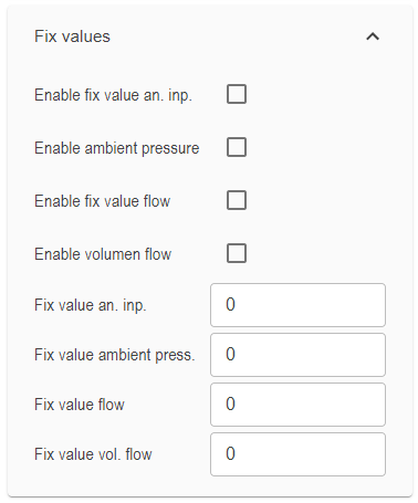
Fix values
Fix values can be enabled/disabled and the value be set for the following parameter
•Analog input
•Ambient pressure
•Flow
•Volume flow
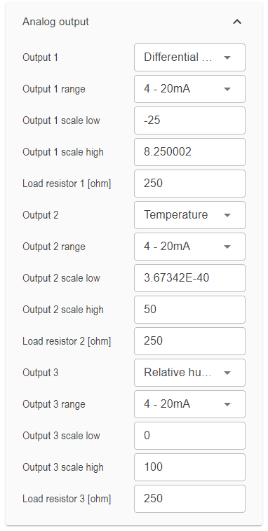
Analog Out
•Output x - a measurement parameter can be linked to the chosen analog output.
•Output x range - the user can chose optional between 0-1Vc, 0-5V, 0-10V, 0-20mA, 4-20mA.
•Output x scale low/high - the low and the high value of the measurement parameter is linked to the low and the high range value. E. g. -50Pa -> 4mA and +50Pa -> 20mA.
•Load resistor x [ohm] - Ohmic resistor for the current output used by the device integration at the customer. It is between 0 and 500Ohm.
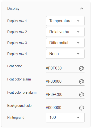
Display
•Display row x - the measurement value can be linked to the display row.
•Font color - user can chose the color of the displayed measurement value/unit.
•Font color alarm - user can chose the color of the displayed measurement value/unit at alarm.
•Font color pre alarm - user can chose the color of the displayed measurement value/unit at pre alarm.
•Background color - can be set by the user.
•Brightness - can be chosen between 20 and 100.
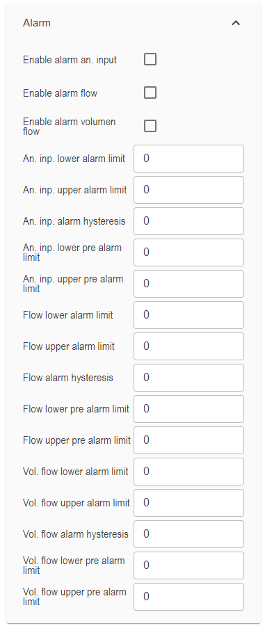
Alarm
•Device alarms of each measurement parameter can be enabled/disabled
•Lower, upper alarm limit and hysteresis of each measurement parameter can be defined
for the following parameter
•Analog input
•Ambient pressure
•Flow
•Volume flow
Relay
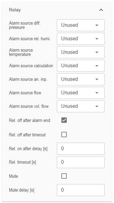
The following configurations can be set for Relay 1-6.
•Relay alarm source x - For each parameter, the user can chose what event switchs the relay on (low alarm, high alarm, low and high alarm or unused)
•Relay off after alarm end - The relay is released with the end of the alarm.
•Relay of after timeout - The relay releases after a timeout independent if the alarm still exists or not.
•Relay on after delay [s] - The relay switches on with a delay after the alarm occurs.
•Relay timeout [s] - The relay switches on with an alarm and off again after the Relay timeout.
•Mute enable/disable - This option enabled mutes an active alarm after the mute delay (see below).
•Mute delay [s] - Time delay after an active alarm is muted.
Analog input
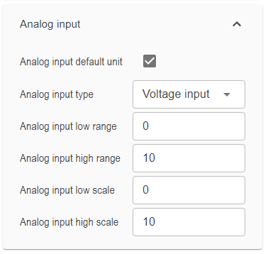
•Analog input default unit - The user can chose between a default or an individual unit for the analog inputs. The default displays V or mA.
•Analog input 1/2 input type - Chose of voltage or current input.
•Analog input low/high range - the min./max. analog input signal is defined.
•Analog input 1/2 low/high scale - to the low/high range above, the low/scale of the measured value is linked. E. g. 400ppm CO2 concentration = 4mA analog input and 10000ppm = 20mA.
Ethernet
Note: The PF4/5 can not be communicate with the Hygrosoft via RS485. The Hygrosoft can only configure the device.
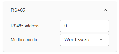
•RS485 adderess
•Modbus mode - Word swap, Byte swap, Byte and word swap, No swap
RS485
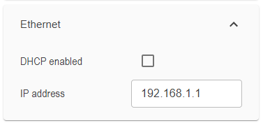
•DHCP enabled/disabled
•IP address - Necessary, if DHCP is disable.
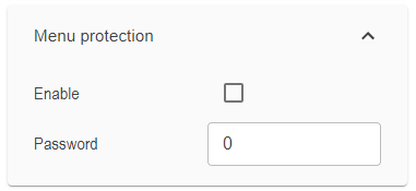
Menu protection
If the menu protection is active, the user can only read device information on the device display. He cannot change device settings.
•Menu protection enabled/disabled
•Password - can be set.
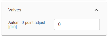
Valve
•Autom. 0-point adjust [min] - this feature performs a 0-point adjustment of the differential pressure sensor to compensate long term drifting. This feature can enabled and repeated automatically every set minutes. 43200 is default is stands for every 30 days.
Note: This feature is supported only for the PF5. This feature has no effect on the PF4 operation. The PF4 executes an 0-point correction every measurement interval automatically and sensor internally.
Flow
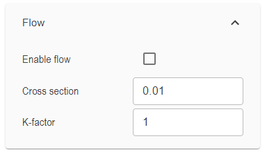
•Enable flow parameter
•Cross section – see CRP5
•K-Factor – value between 0 – 1. Quotient between max. measureble flow and the average flow over the cross section. As bigger the cross section is as closer the K-factor to 1 is.
Further function
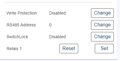
•Write protection - enable/disable and password
•RS485 address - 1-63
•SwitchLock - keys are blocked or release (default)
•Relay 1 - manual set and reset
Differential pressure
The CRP has the possibility to acquire and then adjust multiple adjustment points for differential pressure, humidity and temperature.
For differential pressure it's possible to adjust up to 31 measurement points.
The
For the humidity it's possible to adjust up to 100 measurement points.
For the temperature it's possible to adjust up to 2 measurement points.
Adjustment
The PF4/5 has the possibility to acquire and adjust 31 differential pressure values.
For the humidity it's possible to adjust up to 100 measurement points.
For the temperature it's possible to adjust up to 2 measurement points.
