Desiccant Reservoir
The desiccant reservoir should be filled up to the inside lip - this will require approximately
50cm3 of desiccant.
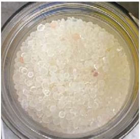
When fresh, the desiccant will be orange.
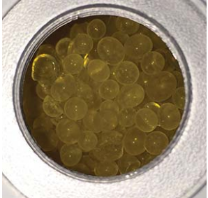
As it becomes exhausted, it will lose its color and become clear.
To replace the desiccant, it is preferable to empty the chamber by use of a vacuum cleaner.
The desiccant can be regenerated by emptying it completely from the desiccant chamber
and drying it in an oven for approximately 3 hours at 130°C (266°F), ensuring that it
is spread out across a tray. After drying it in an oven, allow the silica gel to cool before refilling the desiccant chamber.
Alternatively spare desiccant can be ordered in two different package sizes:
Quantity |
Order Code |
|---|---|
250g |
A000171 |
3kg |
A000172 |
Saturator Reservoir
The saturator should be fi lled up to approximately 20mm below the lid. The water level in the saturator will reduce over time as it is consumed in the process of humidifying the chamber.
NOTE: Always remove water from the saturator reservoir before transportation.
To remove water - Remove the saturator lid and use the syringe provided to remove the water from the reservoir.
Replacing the Internal Reference Sensor
The internal reference is a Rotronic HygroClip 2 Advanced control sensor.
A replacement can be ordered from your local Rotronic / PST representative, using the part number: HC2A-S
To replace the sensor:
1.Loosen the two screws securing the service panel to the rear of the unit.
2.The reference sensor is attached to the service panel, and sealed into the control chamber by an O-ring. Gently pull the panel away, removing the HC2A-S control sensor from the chamber.
3.Unscrew the collar at the base of the HC2A-S, then pull the HC2A-S away from the connector which attaches it to the service panel.
4.The replacement control sensor can then be installed in its place.
5.After installing the replacement sensor, it will be necessary to enter the Calibration Correction Screen to reset the default correction values. This will prevent old correction values being incorrectly applied to the new sensor.
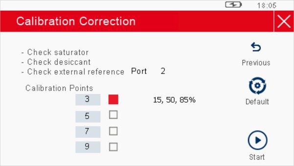
Calibration Correction
The HygroCal100 is provided with an intuitive calibration correction system which is used to calibrate and adjust the internal HC2A-S control sensor against an external reference device.
If a traceable reference is available, it is advisable to pass the traceability of this onto the control sensor of the HygroCal100 at regular intervals. The process allows calibration at 3, 5, 7 or 9 preset points, which are:
Preset |
RH Points |
Total time to complete |
|---|---|---|
3 point |
15, 50, 85% |
45 min |
5 point |
10, 25, 50, 75, 90% |
1 h 15 min |
7 point |
10, 25, 35, 50, 65, 75, 90% |
1 h 45 min |
9 point |
10, 20, 30, 40, 50, 60, 70, 80, 90% |
2 h 15 min |
Select System Settings -> Correct. This will display a prompt to enter a password to proceed - the required code is 7316. Once this has been entered, the Calibration Correction Setup Screen will be displayed. This screen shows a number of checks which should be carried out before proceeding.
NOTE: If the desiccant is exhausted, or the saturation is not sufficiently filled, then this can result in an invalid correction being applied to the control sensor.
NOTE: Ensure that the temperature of the environment you intend to operate in is stable before proceeding.