Unpacking
The HygroCal100 Advanced will be supplied in a carry case (if this option was selected) or in a cardboard box.
If the HygroCal was ordered with a carry case:
1.Remove the carry case from the packing box.
2.Open the carry case.
3.Remove the instrument and place on a level surface.
If the HygroCal was ordered without a carry case:
1.Remove the instrument and accessories box from the packing box.
2.Place the instrument on a level surface.
Save all the packing materials for the purpose of returning the instrument for recalibration or any warranty claims.
The accessories box or (optional) carry case should contain the following items:
•HygroClip calibration certificate / QR-Code for scanning to access online to the calibration certificate
•Power adapters
•Port adapter tool
•Port adapters (optional)
•Desiccant and water bottles (optional)
If there are any shortages please notify Rotronic or PST immediately.
If an additional Calibration Kit has been ordered, then a separate box will also be supplied with the HP32-A-Ref-Set containing the reference instrument. The specific port adapters for the reference will be in the accessories or (optional) carry case with any other port adapters ordered.
Operating requirements
Environment requirements
It is important to operate the HygroCal100 within the following environmental conditions:
Minimum operating temperature +5°C (+41°F)
Maximum operating temperature +40°C (+104°F)
Maximum relative humidity 95%
Electrical Requirements
The power adapter for the HygroCal100 requires the following electrical supply: 100 to 240 V AC, 50/60 Hz
Exterior Layout
The controls, indicators and connectors associated with the HygroCal100 Advanced are located on the front, top and rear panels of the device.
Front Panel
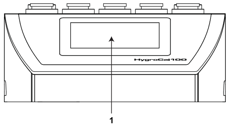
1 |
Touch screen display |
Displays measured readings and enables the user to control the operation of the chamber |
Top Panel
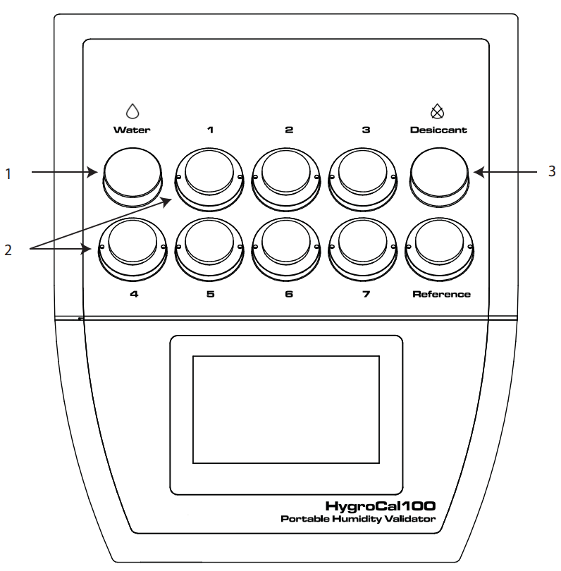
1 |
Saturator reservoir |
Contains a diffuser and distilled water used to humidify the air in the chamber. |
2 |
Probe ports |
Used to mount probes under test into the chamber. |
3 |
Desiccant reservoir |
Contains desiccant used to dry the air in the chamber. |
Rear Panel
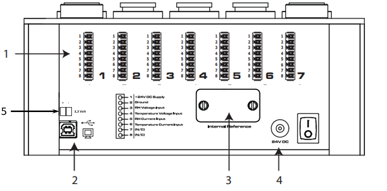
1 |
Probe input connections |
Connections for probes under test. |
2 |
USB communications port |
Allows the HygroCal to be connected to a PC, outputting the relative humidity and temperature values of both the reference probes and the probes under test. |
3 |
Service access port |
Remove for replacement of HC2A control probe. |
4 |
Power adapter input |
24 V DC input. |
5 |
HygroClip power supply |
3.3V power supply specially for the HygroClip. |
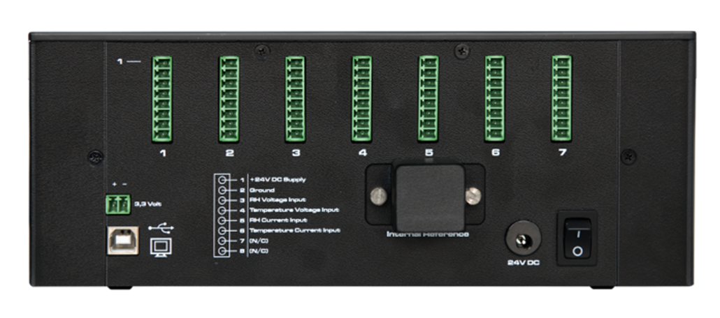
Rear Panel Layout
NOTE: These tasks should only be undertaken by qualified personnel.
Connections to the rear panel of the chamber are explained in the following sections:
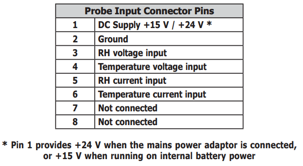
Probe Input Connections
Seven 8-pin connectors are provided to allow connection of probes under test. Probes with a voltage or current input can be connected.
USB Communications Port
The USB type-B connector on the rear panel allows the HygroCal to be connected to a PC and the HC100A ServiceTool.

When connecting the port to a PC, the device will be installed as a virtual serial port, and assigned its own COM port number, allowing communication with many different engineering programs and programming languages.
The output will be in the following format:
InternalReferenceRH Probe1RH Probe2RH Probe3RH Probe4RH Probe5RH Probe6RH Probe7RH |
InternalReferenceTP Probe1TP Probe2TP Probe3TP Probe4TP Probe5TP Probe6TP Probe7TP |
0100 0114 FFFF 0115 FFFF FFFF FFFF FFFF 00E9 00E4 FFFF 00E3 FFFF FFFF FFFF FFFF |
Each 2 byte hex word is a 16 bit unsigned integer, which should be divided by 10 to give
the actual decimal value of the associated reading.
e.g. Internal Reference RH value 0x0100 = 256. Dividing this value by 10 gives the %RH value 25.6%.
Service Access Port
The service access port has a cover which can be removed to access the HC2A-S control sensor for replacement (see replacement instructions in Maintenance).
The cover is held in place by two flat-head screws.

Power Adapter Input
The DC power connector is a push fit into the power input socket.
The method of connection is as follows:
1. Ensure that both ends of the power cable are potential free, i.e. not connected to an AC power supply.
2. Check that the ON/OFF switch is switched to OFF.
3. Push the connector into the power input socket.
4. Connect the mains plug of the power adapter to a suitable AC power source (voltage range 100 to 240 V AC, 50/60 Hz) and switch on the AC supply.
5. Switch on the instrument, as required, using the power ON switch.

Top Panel Layout
Probe Ports
Seven ports are provided for the installation of probes under test. Each port is fitted with an adapter, which allows the probe to be sealed into the chamber by means of an O-ring.
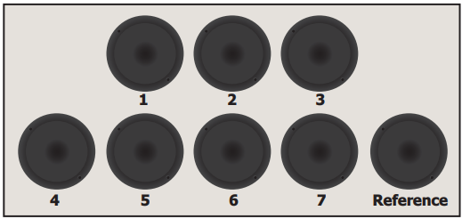
Adaptors are available with a wide variety of port sizes, from 12 to 25mm.
To install a port adapter, locate the port adapter removal tool (A000265) in the pin holes on each adapter, and unscrew or tighten the adapter into the port. Take care not to crossthread the adapters.
To install a probe, simply fi t the correct size of port adapter, remove the blanking plug, and push the probe straight through the center of the adapter until the O-ring grips the probe shaft at its widest point. Ensure that any ports not in use are blanked off with the appropriate plug.
Desiccant Reservoir
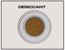
The desiccant reservoir should be filled with the desiccant provided before operation:
1. Remove the lid.
2. Pour in fresh desiccant until the level is 10mm from the top.
3. Re-fit the lid.
The desiccant chamber requires 50cm3 of desiccant to fill, which is approximately equivalent to filling up to the inside lip.
Saturator Reservoir
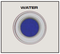
The saturator provides the source of humid air for the chamber.
Distilled water should be added to the saturation before operation. The saturator should only be fi lled with distilled water - no more than 30ml total.
NOTE: Always remove water from the saturator reservoir before transportation.
Adding water:
Power off the HygroCal100. Remove the lid and use the syringe supplied to add water to the reservoir. Fill gradually until the stable water level sits approximately 20mm below the lid. Replace the lid.
Removing water:
Power off the HygroCal100 and place on a flat, stable surface with the back panel facing down. Remove the saturator lid and use the syringe provided to remove the water from the reservoir.