Once fi lled with water and desiccant, the HygroCal100 Advanced is ready for operation. This section describes both the general operation of the chamber and the method of setting it up and changing the default parameters should this become necessary.
General Operational Information
The chamber should be placed on a level surface in an environment with as stable an ambient temperature as possible. When moving the device from one place to another leave for 30 minutes to 1 hour in the new location to allow the temperature of the HygroCal100 Advanced to equilibrate with the prevailing ambient. If the unit has been moved from an environment with a very different temperature (i.e. from outside on a winter's day to inside), it can be benefi cial to remove the port adapter plugs from the chamber and run it in standby mode for this time to allow ambient air to diffuse around the chamber interior more freely.
The HygroCal100 is suitable for verifying any relative humidity sensor, provided that it can be tightly sealed into the chamber.
Display
The HygroCal100 features a 4.3" colour touch screen display.
When the chamber is switched on the screen will initially be blank while the menu system loads.
After the menu system has loaded, the Main Screen will show.
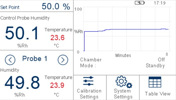
Main Screen Layout

1 |
Relative Humidity Set Point |
Indicates the target RH set point. |
|---|---|---|
2 |
Reference Readout |
Displays the RH and temperature readouts of the selected reference sensor. |
3 |
Probe Selection |
Switches between the currently connected probes. |
4 |
Probe Readout |
Displays the RH and temperature readouts of the selected probe. |
5 |
Power Status Indicator |
Displays the current power source and battery charge level. |
6 |
Stability Graph |
Displays a plot of RH over time. Touch and hold the readout to enter full screen mode. |
7 |
Operational Status Display |
A detailed description of each item displayed in this area is down below. |
8 |
Calibration Settings Button |
Access to the Calibration Settings Menu. |
9 |
System Settings Button |
Access to the System Settings Menu. |
10 |
Table View Button |
Access to the Table View Screen. |
Menu Structure
Current Set Point
The target relative humidity level can be changed by pressing the Set Point pane in the top left of the main screen. This is only possible when Calibration Settings -> Mode is set to Manual.
Probe Selection
The probe selection pane on the Main Screen can be confi gured to show the relative humidity and temperature readings of any of the connected probes.
To cycle through the connected probes, touch the left or right arrow keys on either side of the probe number indication.
Operational Status Display
The Operational Status Display includes the following:
Chamber |
Indicates the operational condition of the chamber. Options: RESPONDING, STABILIZING, STABLE or OFF |
|---|---|
Mode |
Indicates the operating mode of the chamber. Options: MANUAL, AUTO or STANDBY |
Next Point |
When the conditions in the chamber are stable this will indicate the time remaining until the next set point. |
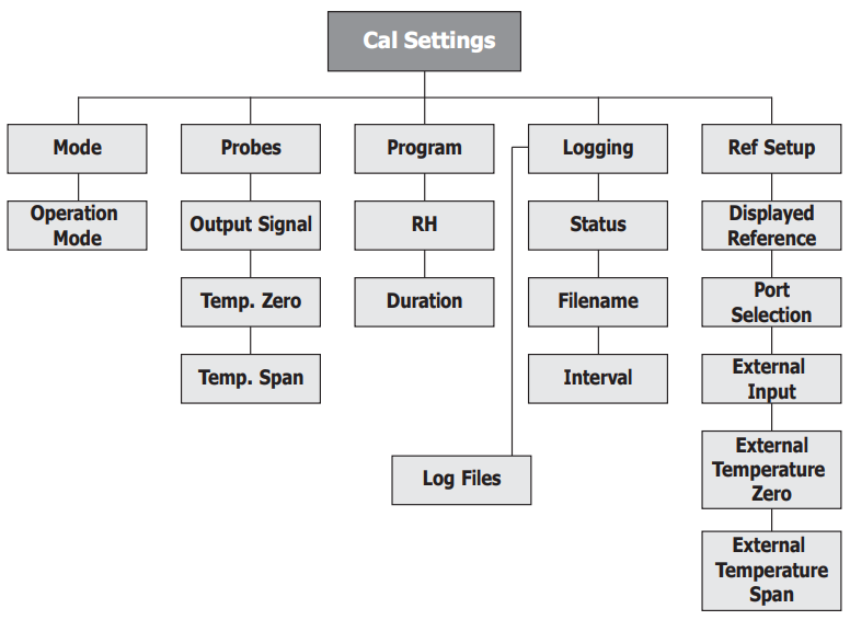
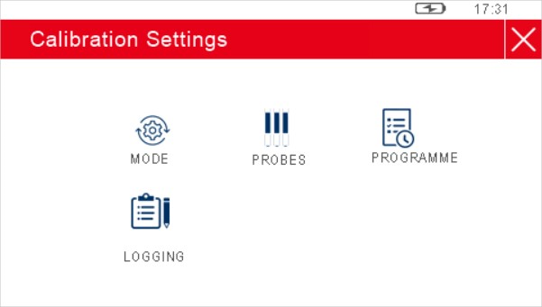
Calibration Settings
The Calibration Settings Screen is used to configure the probes under test, the calibration routine to be followed and the data logging feature.
Initially, when the Calibration Settings Screen is opened, a set of labeled icons is displayed. Touching once of these icons will take you to the appropriate submenu.
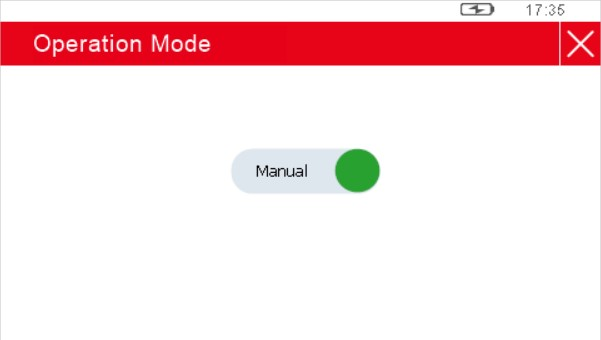
Mode
Parameter |
Description |
|---|---|
Operation Mode |
Determines whether the chamber is controlling manually according to the target set point on the Main Screen, automatically according to an entered calibration routine, or remaining in standby mode. Available Input: Manual/Auto/Standby |
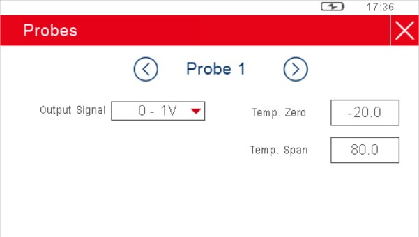
Probes
Parameter |
Description |
|---|---|
Probe # |
Scrolls through the probe ports using the left and right arrows |
Output Signal |
The output signal used by the probe currently selected Available Input: 0-20 mA, 4-20 mA, 0-1 V, 0-5 V, 0-10 V |
Temp. Zero |
For this probe # - Sets the temperature which corresponds to a zero output Available Input: Numerica |
Temp. Span |
For this probe # - Sets the probe temperature which corresponds to a span output Available Input: Numerica |
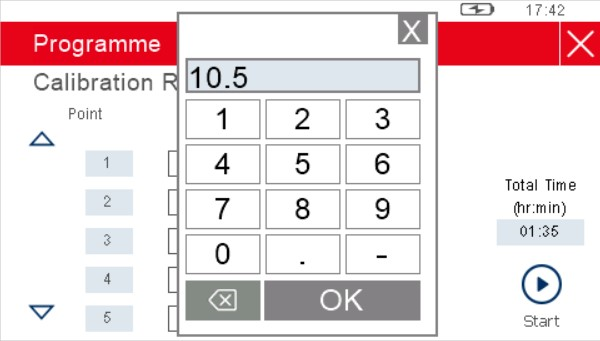
Program
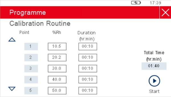
The table provided in the Calibration Routine Screen allows a series of relative humidity points to be generated for set time periods without intervention by the user.
Each row of the table defines a calibration point, with fields to enter the desired relative humidity value and the length of time the chamber should spend maintaining this humidity.
Once this period of time has elapsed, the chamber will move to the conditions on the next row. There can be a maximum of 10 calibration points in the routine.
NOTE: The 'Duration' only starts when the chamber has stabilized at the desired condition.
To initiate the calibration routine, touch the Start button.
At this point, if logging is not in progress, then a prompt will appear to confirm whether or not logging is required.
If NO is selected, then the program will start and the display will return to the Main Screen.
If YES is selected, then the Logging Screen will be displayed. Once data logging has been initiated the program will run.
Logging
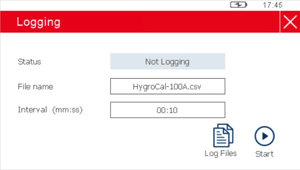
Parameter |
Description |
|---|---|
Status |
Shows whether logging is active or not. Available Inputs: None |
File name |
Sets the name for the next log file. Available Input: Tex |
Interval |
Sets the frequency at which logged data will be collected. Available Inputs: Time in minutes and second |
Once a file name has been set, logging can be initiated by touching the Start button.
The Log Files Screen can also be accessed from here.
NOTE: Enter the log file name as one word with NO spaces.
Log Files
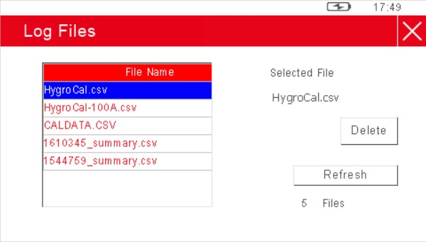
This screen allows management of the log files currently stored on the HygroCal100 Advanced.
Each of the log files is listed as its own row in this screen, the rows are scrollable by means of the up and down arrows located on the left-hand side. The rows also have tick boxes, which can be used to highlight each independently.
Alternatively the Delete: All key can be used to wipe all logged data from the device.
Reference Setup
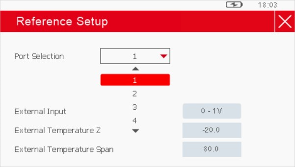
Parameter |
Description |
|---|---|
Displayed Reference |
Chooses to display the readings of either the internal control sensor or an external device as the reference. Available Input: Internal, External |
Port Selection |
Selects the probe port if the external reference is connected. |
External Input |
Selects the output signal if the external reference is connected. Available Input: 0-1V, 0-5V, 0-10V, 0-20mA, 4-20mA |
External Temperature Zero |
Sets the temperature which corresponds to a zero output if the external reference is connected. Available Input: Numerical |
External Temperature Span |
Sets the temperature which corresponds to a span output if the external reference is connected. Available Input: Numerical |