The HF4 series offers the following user functions:
•User configurable settings
•Calculation of the dew or frost point
•Humidity temperature calibration and adjustment
•Simulator mode
Variants
HF4 transmitters with analog output signals:
Two types of electronic circuit are available:
•HF42: 2-wire, loop powered (4…20 mA current signal)
•HF43: 3-wire (voltage or current signal).
Both circuit types provide linear analog outputs signals for transmission over a length of cable to a remote display, recorder, controller or data processing unit and can be used to measure humidity only, temperature only or both parameters.
Display option and keypad option
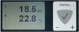
The LC display option for the HF43 has a backlight. The LC display option for the HF42 does not have a backlight. The upper line corresponds to relative humidity or dew / frost point and the bottom line corresponds to temperature.
The display can be configured to show a trend indicator on each line:
▲: increasing value
▼: decreasing value
In the event of an alarm the display shows the symbol [ ! ] to the right of the value.
For instructions see the following HW5 or HygroSoft manual.
Safety
It is important to comply with the manufacturer its instructions. If these instructions are not complied with, the safety characteristics of the HF4-device can be influenced.
Power supply
Depending on the circuit type, the H43 requires the following power supply:
HF42 |
2-wire, loop powered |
10…28 VDC - depending on the load connected to the output(s). The minimum supply voltage can be determined as follows:
V min = 10 V + (0.02 x Load*) *Load resistance in Ω.
For the maximum load of 500 Ω, the minimum supply voltage is 10 + (0.02 x 500) = 20 VDC. With both output circuits closed, the maximum current consumption is 40 mA. |
HF43 |
3-wire, analog outputs |
||||||||||
18 to 40 VDC (see note below) or 13 to 28 VAC. With both output circuits closed and enabled backlight, the maximum current consumption is 100 mA for DC powered devices and 260 mA for AC powered devices.
Note: depending on the type of output signal, the HF43 will operate with the following minimum voltage
|
Measured parameters
The HF4 measures relative humidity with a ROTRONIC Hygromer® IN-1 capacitive sensor and temperature with a Pt100 RTD.
Calculated parameters
Using the ROTRONIC HW5 or HygroSoft software, the HF4 can be configured by the user to calculate either the dew point or the frost point.
Analog output signals (HF42 and HF43)
HF42 and HF43:
With the ROTRONIC HW5 or HygroSoft software any of the two analog output signals can be made to correspond to one of the following:
• Relative humidity
• Temperature
• Dew or frost point
Any output can also be disabled.
The scale of each analog output can be set within the numerical limits of -999.99 and 9999.99.
The D/A converters used to generate the analog output signals feature a 16-bit resolution and exhibit a small positive offset at the bottom of the signal range as indicated below:.
Signal type |
Maximum offset at range bottom |
0…1 V |
10 mV |
0…5 V |
50 mV |
0…10 V |
100 mV |
0…20 mA |
0.2 mA |
4…20 mA |
No offset |
HF43:
The ROTRONIC HW5 or HygroSoft software allows changing the type of output signal to one of the following: 0…20 mA, 4…20 mA, 0…1V, 0…5V or 0…10V. Both output signals are automatically configured with the same signal type. No calibration or adjustment is required after changing the type of output signal.
In the case of voltage output signals, load requirements apply to the external device or circuit connected to the HF43 transmitter. These requirements are defined in the “Operating modes and wiring” chapter
Service connector
The service connector is a UART digital interface (Universal Asynchronous Receiver Transmitter) with a mini-USB type connector. This allows connecting the HF4 either to a PC running the ROTRONIC HW5 or HygroSoft software or to a probe input of another instrument that is compatible with the HygroClip Advanced (HC2A) probes. In both cases a service cable is required. See “ Maintenance” for the location of the service connector and for the type of service cable to be used.
•Connecting the HF4 to a PC is used to configure the HF4, gain access to the HF4 functions such as humidity and temperature adjustment, read data from the HF4 on the PC and update the AirChip3000 firmware.
•Connecting the HF4 to the probe input of another instrument is useful only when the other instrument has its own display and keypad, and has an internal menu equivalent to the menu of the HP23 hand-held calibrator. The connection allows showing the data measured by the HF4 on the other instrument display and also allows using the other instrument internal menu to do for example a humidity and temperature adjustment of the HF4.
Sensor protection (dust filter)
The HF4 is supplied with a Polyethylene filter to protect the sensors against dust particles and high air velocity.