The safety of the installed system, where the device is integrated, is the responsibility of the builder of the system.
General wiring guidelines
Power supply wiring
Heavy machinery and instrumentation should not share the same power supply wiring. If this cannot be avoided, noise filters and surge protectors should be used. Most UPS devices have those features already integrated.
General guidelines for signal cables
The following guidelines are derived from European Standard EN 50170 for the transmission of signals by copper wires. When planning an installation, the rules provided by EN 50170 should be followed under consideration of local circumstances to determine the position of machines and equipment.
All ROTRONIC products are tested for Electromagnetic Compatibility according to EMC Directive 2004/106/EG and following European standards:
- EN 61000-6-1: 2001, EN 61000-6-2: 2005
- EN 61000-6-3: 2005, EN 61000-6-4: 2001 + A11
Whenever the level of electromagnetic interference is expected to be high, both the instruments and signal cables should be placed as far away as possible from the source of interference.
In general, signal cables should be installed in bundles or channels / conduits, separate from other cables as indicated in the table below:
•Bus signals such as RS485 •Data signals for PCs, printers etc. •shielded analog inputs •unshielded direct current (<= 60V) •shielded process signals (<= 25 V) •unshielded alternate current (<= 25V) •coaxial cables for CRT monitors |
in common bundles or channels / conduits |
•direct current from 60 V to 400 V (unshielded) •alternate current from 25V to 400 V (unshielded) |
in separated bundles or channels / conduits, without minimum distance |
•direct and alternate current > 400 V (unshielded) •Telephone lines •lines leading into EX-rated areas |
in separated bundles or channels / conduits, without minimum distance |
Lightning protection
Cabling in areas with a risk of lightning requires a lightning protection. For cabling underground in between buildings, we recommend the use of special fiber optic cables. If this is not possible, use copper cables that are suitable for underground installation.
Cable grip and cable specifications
The HF4 is supplied either with one M16 sealing cable grip or with a ½” conduit adapter. The M16 cable grip provides effective sealing only with cables having the proper outside diameter. Preferably, use a cable with an outside diameter of 6 to 7 mm (0.236 to 0.275 inch) with 18 AWG wires.
Wiring
HF42: 2-wire, loop powered transmitter
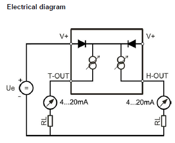
The maximum permissible cable length connecting the HF42 to other devices is determined by the total resistance resulting from the addition of the cable resistance and that of the devices connected in series with the unit. This resistance should not exceed 500 ohms.
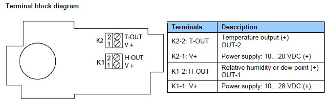
Note: connect the + of the power supply to only one of the V+ terminals. The two terminals marked V+ are internally connected.
Measuring humidity or temperature only
Unless configured to measure either humidity only or temperature only, proper operation of the HF42 requires both current loops to be closed. The HF42 can be directly ordered from the factory to measure either humidity or temperature only. When necessary, any unused output of the HF42 can be disabled with the ROTRONIC HW4, HW5 or HygroSoft software. When the HF42 is configured with one of the two outputs disabled, close only the loop that is being used.
HF43: 3-wire transmitter
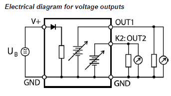
The maximum permissible cable length can be determined under consideration of the voltage drop caused by the current flowing to the devices connected to the unit. The voltage drop in the cable depends both on cable resistance and on the equivalent resistance of the devices connected in parallel to the unit. The total resistance connected to each unit output should be at least 1000 ohms. Cable resistance should not be more than 1/1000 of the load resistance.
Minimum load requirements apply to the external device or circuit connected to the HF4 transmitter. These requirements are defined in the “ Samples of possible operating modes” chapter.
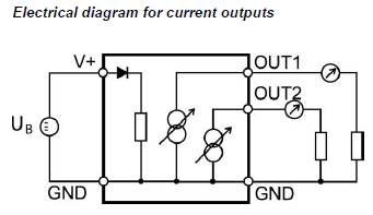
The maximum permissible cable length, connecting the unit to other devices, is determined by the total resistance resulting from the addition of the cable resistance and that of the devices connected in series with the unit. This resistance should not exceed 500 ohms.
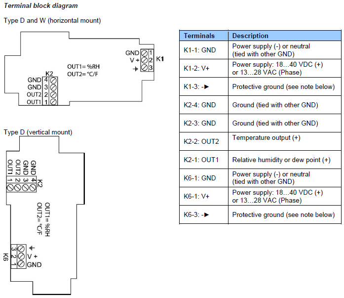
Note: Terminals K1-3 or K6-3 (protective or earth ground) are tied with GND. If this is not wanted, a land (B18) on the PCB must be removed.
Measuring humidity or temperature only
Operation of the HF43 does not require both current loops to be closed. When using the HF43 to measure either humidity only or temperature only, close only the loop that is being used.
Using the ROTRONIC HW5 or HygroSoft software, any unused output of the HF43 can be disabled.
Grounding (all models)
We generally recommend grounding the (-) side of the power supply, especially if the electronics will be subjected to a low humidity environment (35 %RH or less).