Step 1 |
Connect the probe to a laptop/PC with an AC3001 cable. Click on add Device>Search>Local Devices and select the device settings. |
Step 2 |
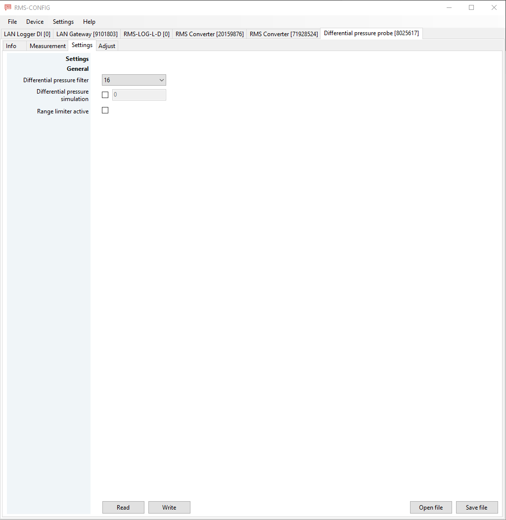
Differential pressure filter: The differential pressure probe has a low pass filter included to reduce noise on the measured value. Possible values are 0, 2, 4, 8, 16 (default). The value represents the number of measurements, which create the basis for the measurement filter (average calculation). This measurement and its average calculation is done in less than 100 milliseconds and within every measurement interval. Due to the fast measurement, we advise to use the maximum filter of 16 (standard).
Differential pressure simulation: The PCD will deliver a fixed simulated value. The probe will show up in RMS with a reminder event: simulator connected.
Range limiter active: The range limiter active will limit the output of the PCD to the sensor limits. For example, a PCD with sensor limits of -25...+25Pa, will show a minimum of -25Pa and a maximum of 25Pa. The device will no longer show any sensor errors within the RMS software but a value of +999.9Pa. A sensor error can appear for the following reasons: •The communication with the probe/sensor is not working. •The communication to the probe/sensor takes too long. •The communication with the onboard pressure sensor is not working. •The wrong sensor type has been built onto the probe.
When this option is selected, the following warning will appear: by selecting this option, an overpressure may not be recognized and may result in the unit being damaged. This damage is not covered by the warranty. |