Installing Relative Humidity Instruments for Calibration
Relative humidity probes can easily be installed into the humidity chamber through
the ports in the door. The amount and size of the ports are supplied per customer
specification.
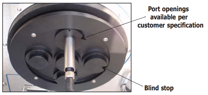
NOTE: Ports which are not being used should be covered with a blind stop
to exclude temperature and relative humidity infl uences from outside the
chamber.
NOTE: If a door without ports (A000268) is used, the probes to be tested
must be placed inside the measurement chamber. To ensure good air fl ow do
not overfi ll the chamber with probes.
The port adapters can be changed using a port adapter removal tool (A000265).
Insert the two pegs on the adapter tool into the corresponding holes on the port
adapter and turn counter-clockwise to loosen and clockwise to tighten.
Start-Up
After installing the instruments for calibration, switch on the S904 Series by using the
ON/OFF switch on the rear panel of the instrument.
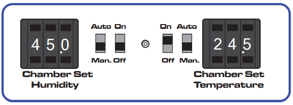
Manual Control of Humidity and Temperature Setting
The desired percentage of relative humidity and temperature (in °C) can be manually
set by using the humidity and temperature setting switches when the AUTO/MAN
switches are in the MAN position. Humidity or temperature control can be enabled or
disabled individually using the associated ON/OFF switch.
NOTE: Sufficient time must be allowed for the S904 Series to thermally
stabilize before monitoring the humidity and temperature readings.
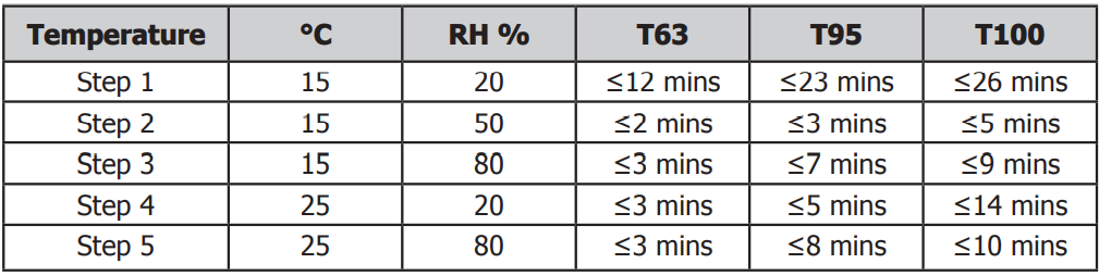
Typical Response Times for Various Step Changes
Typical response times for various step changes are shown in Table 1 below. T100
represents the total time taken to reach stability at the new setpoint.
T63 and T95 values represent the time taken to reach 63% and 95% respectively of
the step change in relative humidity and/or temperature. (Start temperature = 23°C /
Start RH = 50%).
The S904 Series can also be used with relative humidity generation only or with
temperature generation only.
For example: If the calibration of the instruments is complete and new instruments
need to be inserted, both switches can be set to OFF. This will cause the pump to
switch off in order to save energy.
If only temperature calibration is needed, humidity generation can be switched off.
NOTE: In this instance, the pump will also stop.
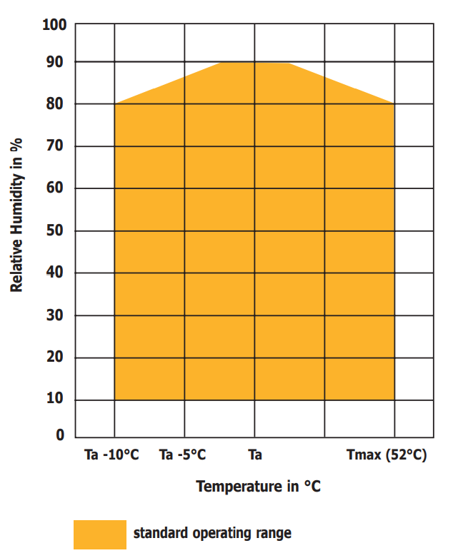
The minimum chamber temperature that can be reached is about 10°C (18°F) below
ambient temperature. The maximum chamber temperature is limited to about +52°C
(+125°F).
Maximum Humidity Levels That can be Generated by the S904 Series
25 pin D-sub Connector - S904
These two connectors provide % RH and temperature outputs from the chamber control
probe. 15 free pins wired from the internal chamber connector to the front panel
connector can be used for any purpose.
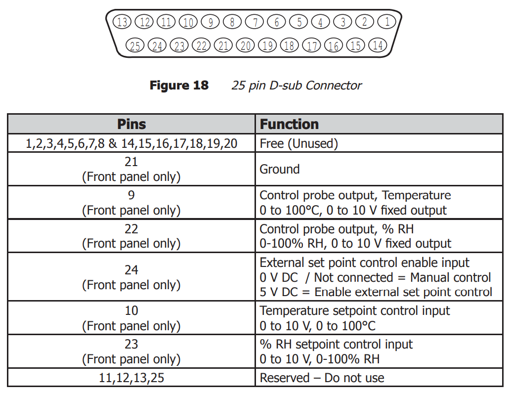
Free (Unused)
These pins are wired from the 25-pin connector inside the chamber to straight through
to the 25-pin connector on the front panel, and can be used for any purpose.
These pins have a maximum current rating of 100 mA, and a maximum voltage rating
of 50 V, which must not be exceeded.
Ground
This pin is connected to the ground of the internal power supply.
Control Probe Outputs, Temperature and %RH
These are fixed 0 to 10 V outputs from the control probe inside the chamber, ranged
from 0 to 100°C and 0-100% RH respectively.
External set point control
To enable external setpoint control, connect +5 V to this pin with respect to ground.
Automatic Control of Temperature and Humidity Set Points - S904
These instructions do not apply to the S904D.
To enable the S904 set points to be controlled using a voltage input:
1.Put the MAN/AUTO switches into the AUTO position.
2.Put the ON/OFF switches into the ON position.
3.Connect +5 V to pin 24 with respect to ground (pin 21) to enable external control of the set points.
The unit is now ready to accept external inputs.
External inputs:
• %RH set point
Pin 23, Input: 0 to 10 V, Range: 0 to 100%
• Temperature set point
Pin 10, Input: 0 to 10 V, Range: 0 to 100°C
NOTE: Connections to the external inputs should be made with respect to
ground on pin 21.
NOTE: The maximum temperature in the climate chamber that can be reached
is 52°C, and the minimum is 10°C (18°F) below the ambient temperature.
25 pin D-sub Connector - Rear Panel and Inside Chamber - S904D
These two connectors provide 6 channels for data acquisition, a +14.5 V supply, ground
connection and 9 free pins wired from the internal chamber connector to the rear panel
connector that can be used for any purpose.
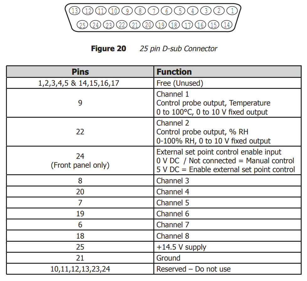
Free (Unused)
These pins are wired from the 25-pin connector inside the chamber to straight through
to the 25-pin connector on the rear panel, and can be used for any purpose.
These pins have a maximum current rating of 100 mA, and a maximum voltage rating
of 50 V, which must not be exceeded.
Channels 1-2
These channels are connected to the built-in RH probe and are always logged by the
S904D Labview® Software.
Channels 3-8
These channels accept a 0 to 10 V input and can also be logged by the S904D Labview®
Software.
14.5 V Supply - PIN 25
This pin is connected to the internal power supply of the S904D and can be used to
provide power to probes inside the chamber.
NOTE: For safety purposes the power supply is fi tted with a thermal cut-out
that is connected to the rear panel 25-pin connector only. It is important that
this thermal cut-out is not bypassed, or the instrument may be damaged in
the event of a fault. Refer to Figures 21 and 22 for detailed drawings showing
how to correctly wire the power supply.
Ground - PIN 21
This pin is connected to the ground of the internal power supply.
Reserved – Do not use - PINS 10, 11, 12, 13, 23, 24
Warning
Applying a current or voltage to the Reserved PINS may cause
permanent, irreversible damage to the S904D electronics.
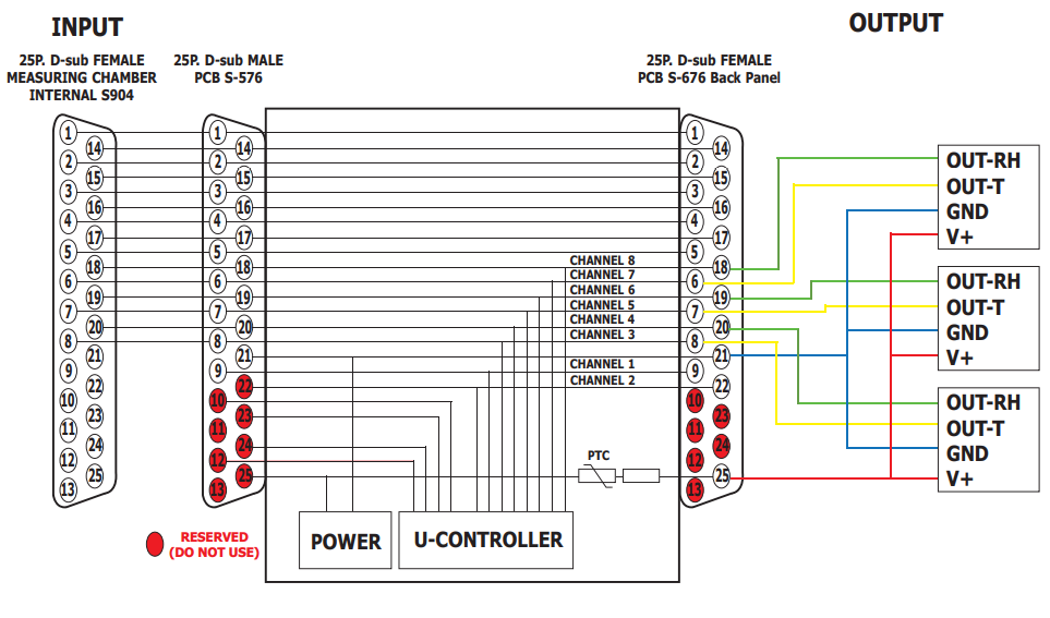
S904D Example Wiring Diagrams
The following diagram shows how to connect three %RH probes using the 25-pin D-sub
connector inside the chamber, and powering the probes using the internal S904D power
supply while logging their %RH and temperature outputs.
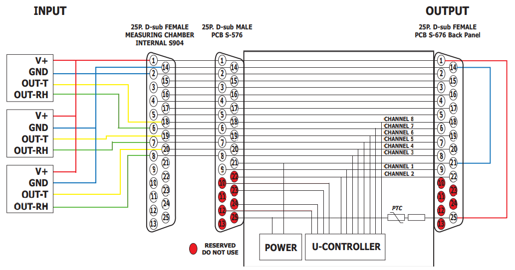
The following diagram shows how to connect three % RH probes using the 25-pin D-sub
connector on the rear panel of the S904D, and powering the probes using the internal
S904D power supply while logging their % RH and temperature outputs.
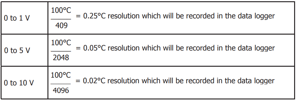
S904D Data Acquisition Resolution
The data acquisition is made for 0 to 10 V input. The AD converter (analog to digital) is 12
bit data acquisition, so there are 4096 steps. If a device is connected with a 0 to 5 V output
the resolution goes down to 2048 steps and for an instrument with a 0 to 1 V output the
resolution goes down to 409 steps.
For example: If an instrument under calibration has an output of 0 to 1 V and the
temperature output range of the instrument is -40 to +60°C, (which is a total range of
100°C) then the resolution is 0.25°C. See the calculations below: