The S904 Series’ enclosure is designed for bench top mounting in a laboratory type
environment. It must be positioned in a clean and level location with sufficient clearance
at the rear of the enclosure for adequate ventilation.
The S904 Series is not designed to be fully portable. However
it can easily be moved to any suitable location for use. Before
moving ensure that any water in the reservoir is drained and the
relative humidity control probe in the chamber is removed.
The S904 Series should NOT be moved while in operation.
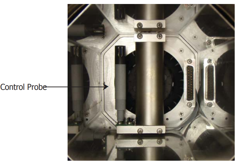
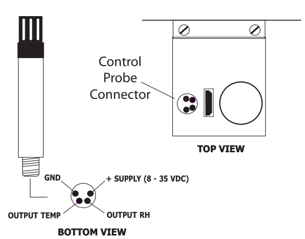
Installing the Relative Humidity and Temperature Control Probe
The HT961T00 Relative Humidity and Temperature Control Probe is supplied as an
accessory with the S904 Series. This control probe is removed during transportation.
To install the control probe remove the chamber door and plug in the probe as shown
in picture below.
This internal control probe is delivered with its own calibration certificate.
The chamber control relative humidity and temperature probe must always be removed during transportation.
Filling the Water Reservoir
Before operation the water reservoir located on the front panel must be filled with distilled water (supplied with the instrument).
Do not use tap water or demineralized water!
Use the bottle supplied to fill the water reservoir.
1.Remove the red plastic cap from the top of the reservoir.
2.Carefully fi ll with clean distilled water to a level between the two indicator lines.
3.Replace the red cap on the water reservoir after filling.
Do NOT fi ll above the MAX indicated line as this may cause liquid
to enter the humidity chamber and adversely affect the control
process.
Draining the Water Reservoir
Drain the water reservoir before transporting, or if the system is accidentally overfilled.
To empty the water reservoir:
1.Remove the red caps from the bottom and top of the water reservoir.
2.Drain the water into a suitable container.
3.Tilt the instrument to empty the reservoir completely.
4.Re-fi t the red cap after emptying.
It is essential to drain the water reservoir before transporting or
when the system is not going to be used for a few weeks.
Do not re-use any of the drained water within the system.
Desiccant
The S904 Series has a container fi lled with a desiccant which is used to dry the air.
The desiccant container can be accessed by following these steps:
1. Remove the clear plastic screw cap on the front panel.
2. Pull out the desiccant container using the finger tips.
3. Fill with desiccant up to the thread
The natural color of the desiccant (dry silica gel) should be orange, or blue (depending
on type). As moisture is absorbed, the color will gradually change to transparent or
pink (depending on type). When the desiccant has become transparent or pink - this
is an indication that the instrument’s ability to generate low humidity is reduced. It is
recommended that the silica gel is replaced or regenerated at this time.
The desiccant can be regenerated by emptying it completely from the desiccant chamber
and drying it in an oven for approximately 3 hours at a temperature of +130°C (266°F).
After drying it in an oven, allow the desiccant to cool before refilling the desiccant
chamber and refitting the chamber into the generator. Ensure that the screw lid is
correctly fitted.
Frequency of desiccant regeneration or replacement is dependent entirely upon the
length of time in operation. Typically, given a normal calibration profile and operation
cycle, the S904 Series can continually generate accurate and stable chamber humidity
for a period of several weeks before regeneration or replacement of the desiccant is
necessary.
Power Supply
A single mains power supply between 100 to 240 V AC is required to operate the unit.
The power supply connection is a 3-pin IEC plug located on the rear panel of the
instrument. The ON/OFF switch and the power input fuse are in the same location,
adjacent to the power socket.
A 3-core power cable is provided.
The instrument must be connected to an electrical earth for
safety purposes.