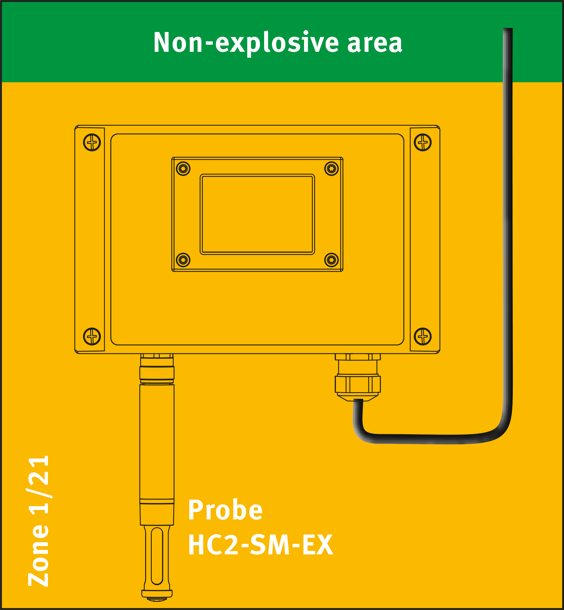
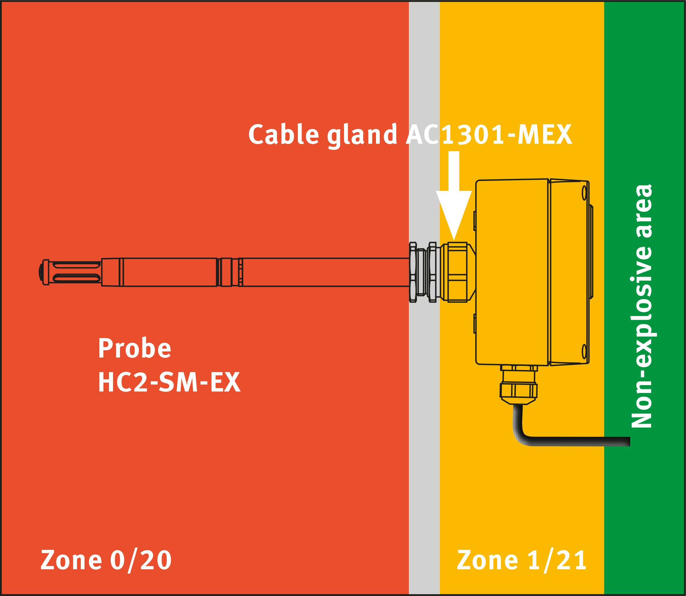
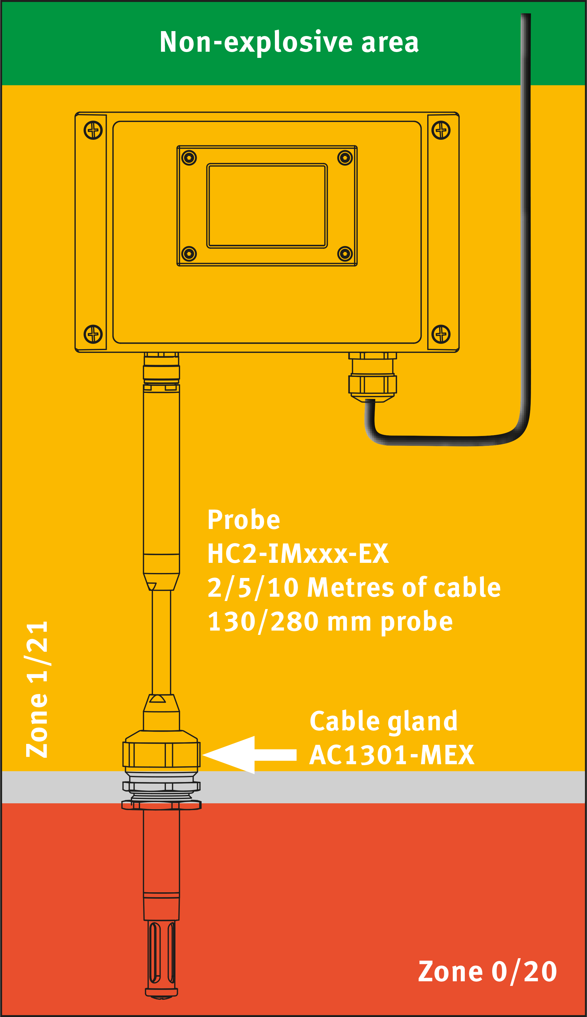
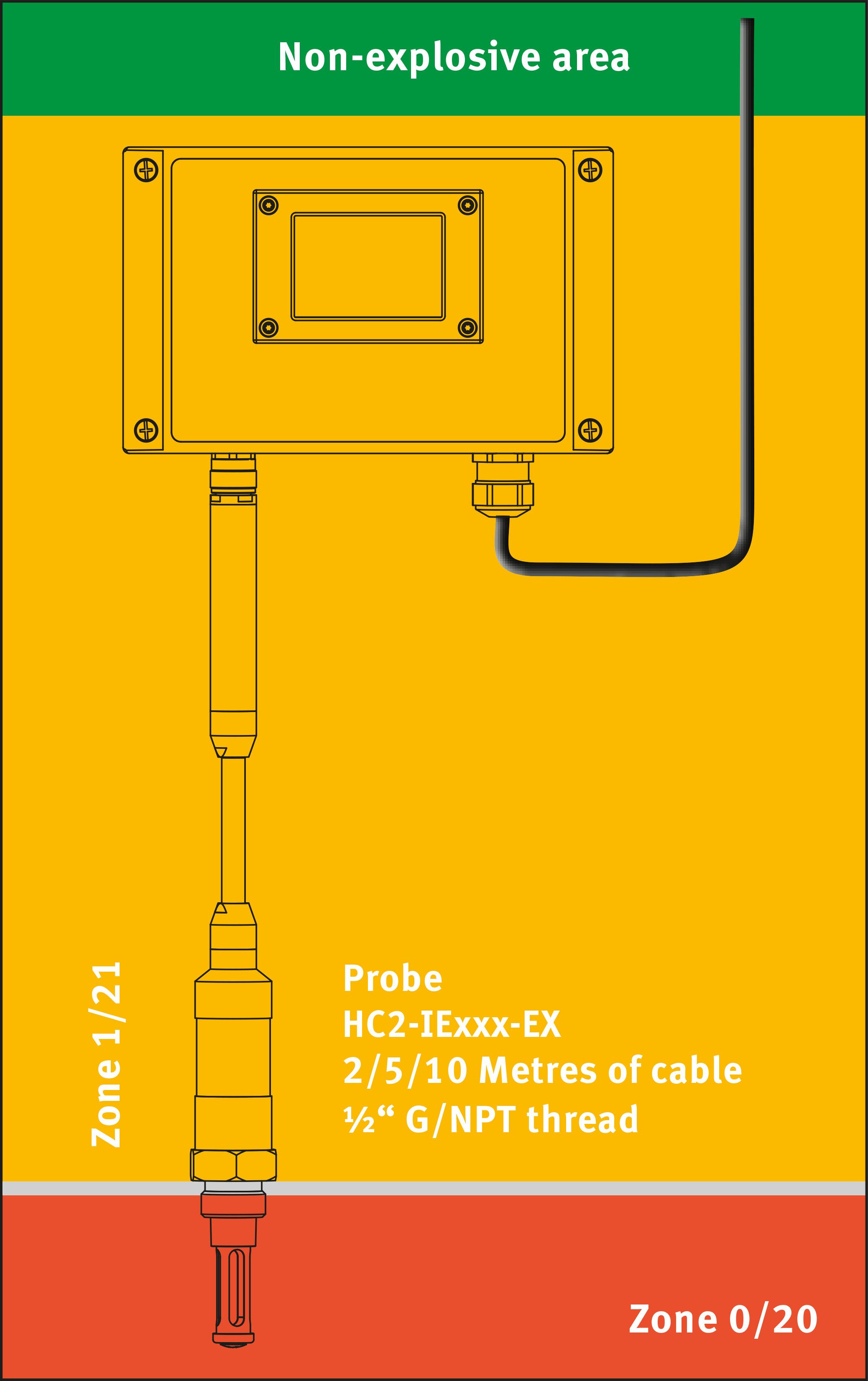
Zone Plan
Applies to gas (Zone 0/1/2) and dust (20/21/22)
Wall Mounting |
Duct Mounting |
|
|
|
|
Use the accessory AC1301-MEX (Mounting gland for 15 mm ATEX probes) for zone separation |
||
Wall Mounting with Cable Probe |
Wall Mounting with Screw-In Probe |
|
|
|
|
Use the accessory AC1301-MEX (mounting gland for 15 mm ATEX probes) for zone separation |
The screw-in probe itself sees to zone separation |
General guidelines
Relative humidity is very dependent on temperature. Proper measurement of relative humidity requires that the probe and its sensor have exactly the same temperature as the environment that is to be measured. For this reason, the location where the probe is installed can have a significant influence on the measuring accuracy of the device.
The following guidelines should guarantee good device performance:
a)Select a representative location: install the probe where humidity, temperature and pressure conditions are representative of the environment to be measured.
b)Ensure there is good air movement at the probe: an air velocity of at least 1 meter/second (200 ft/minute) facilitates quick adaptation of the probe to changing temperature.
c)Avoid the following:
(1) Close proximity of the probe to a heating element, cooling coil, cold or hot walls, direct exposure to sunlight, etc.
(2) Close proximity of the probe to a steam injector, humidifier, direct exposure to precipitation, etc.
(3) Unstable pressure conditions resulting from high air turbulence.
d)Immerse as much of the probe as possible in the environment to be measured.
e)Prevent an accumulation of condensation water in the area of the sensor leads.
f)For this, operate the probe with the probe tip pointing downwards. If this is not possible, install the probe horizontally.
Housing
The housing consists of a base and a cover held together with four screws.
A size 4 flat-tip screwdriver or size 3 cross-tip screwdriver should be used to mount and dismount the cover.
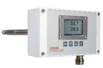
Mounting of the HygroFlex5-EX (Duct Mounting)
HygroFlex5-EX type D (D=Duct)
With / Without keypad and display
Mounting hardware
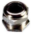
The mounting gland (AC1301-MEX) was developed for fastening of the probe tube of the HF520-EX type D to a duct. The HF520-EX requires no further support.
Mounting of the HygroFlex5-EX (Wall Mounting)
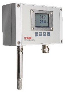
HygroFlex5-EX type W (W=Wall)
With / Without keypad and display
