General Guidelines for Wiring
Power Supply Wiring
Heavy machinery and instrumentation should not share the same electric cables for power supply. If this cannot be avoided, noise filters and surge protectors should be used. Most UPS devices already have these features integrated.
General Guidelines for Signal Cables
The following guidelines are derived from the European standard EN 50170 for the transmission of signals by copper wires. When planning an installation, the rules provided by EN 50170 should be followed under consideration of local circumstances to determine the position of machines and equipment.
All ROTRONIC products are tested for electromagnetic compatibility according to the EMC Directive 2014/30/EU. Please see for more details Conformity on the Rotronic website.
Whenever the level of electromagnetic interference is expected to be high, both the devices and signal cables should be placed as far away as possible from the source of interference.
In general, signal cables should be installed in bundles or channels / conduits, separate from other cables (see table):
• Bus signals such as RS485 • Data signals for PCs, printers etc. • Shielded analog inputs • Unshielded direct current (<= 60 V) • Shielded process signals (<= 25 V) • Unshielded alternating current (<= 25 V) • Coaxial cables for CRT monitors |
in common bundles or channels / conduits |
• Direct current from 60 V to 400 V (unshielded) • Alternating current from 25 V to 400 V (unshielded) |
in separated bundles or channels / conduits, without minimum distance |
• Direct and alternating current > 400 V (unshielded) • Telephone lines • Lines leading into EX-rated areas |
in separated bundles or channels / conduits, without minimum distance |
ATEX Guidelines for Wiring
According to EN60079-14.
According to ATEX, no SELV Power Supply is required. (SELV supply= with limited transients).
Wiring
HygroFlex5-EX: Two-Wire Current Loop, Loop-Powered Transmitter
Connection Terminals |
||
Permitted conductor cross-section (rigid): |
Permitted conductor cross section (flexible): |
Stripping length: |
0.2 mm² ... 4 mm² |
0.2 mm² ... 2.5 mm² |
10 mm |
Terminals |
Description |
K1: CH1- |
Rel. Humidity Output 1 (4…20 mA) |
K1: CH1+ |
Power supply: 10 ... 28 VDC |
K2: CH2- |
Temperature Output 2 (4…20mA) |
K2: CH2+ |
Power supply: 10 ... 28 VDC |
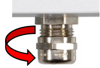
Cable gland |
||
Clamping area: |
Tightening torque: |
|
4.5 – 10 mm (unarmoured cable) |
10 Nm |
|
Only Humidity or Only Temperature Measurement
The transmitter can also be operated with only one closed measurement loop.
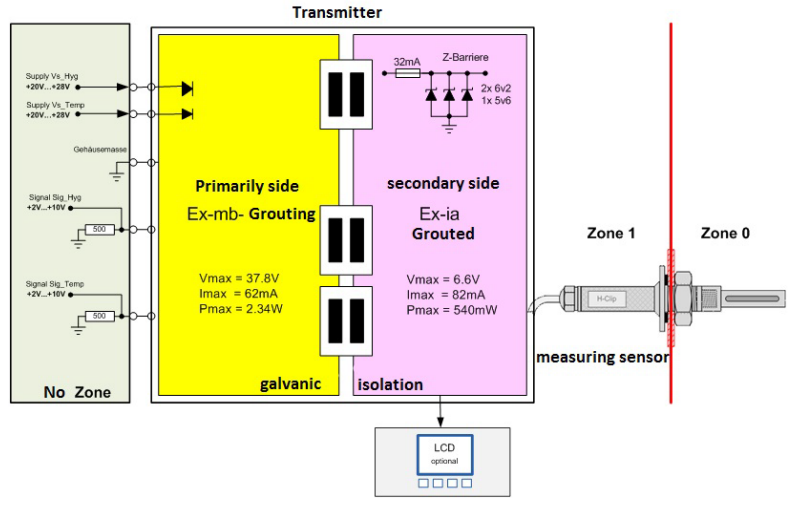
Electrical schematic
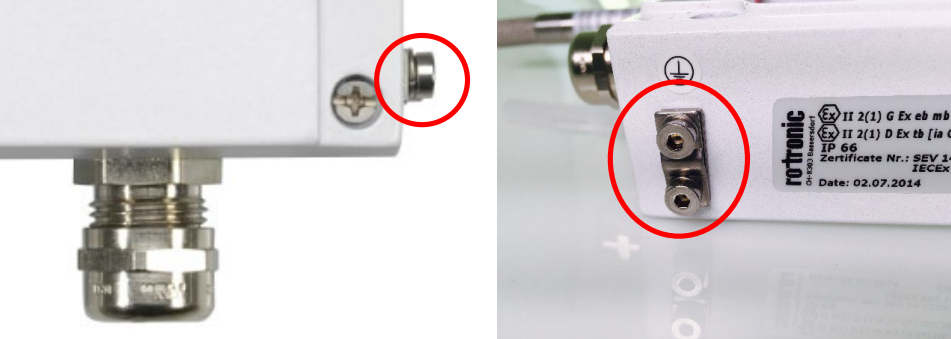
Grounding
The HygroFlex5-EX must be grounded with the ground connection on the housing.