Use a USB cable to connect the USB connector located on the back panel of the HygroLab C1 indicator to the HW5 PC. Unless already installed, you should install the ROTRONIC USB driver on the PC before running HW5.
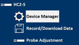
Device Manager
The device manager can be opened for any device in the device tree.
A click opens the following dialog box
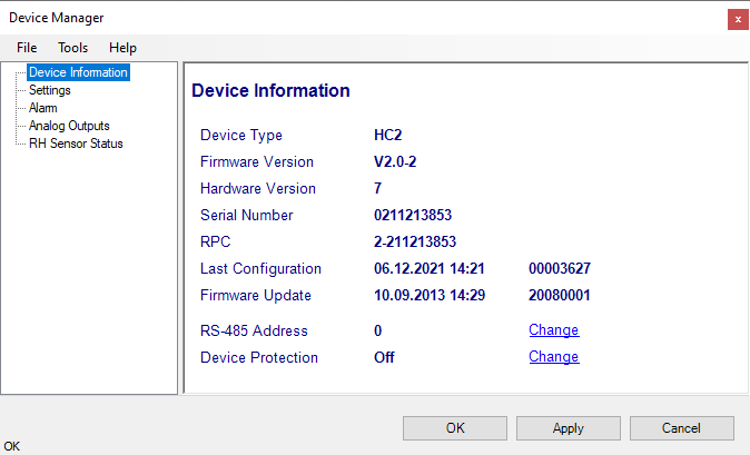
Typically, several device properties and settings are displayed and can be set. This information and settings differ from device to device type.
•Device information
•Settings (name, measurement units, fix values etc.)
•Device Manager of the connected probe
•Analog Inputs and outputs (range and scaling)
•Digital Inputs
•Relay
•Ethernet settings
•etc.
For detailed information, please see chapter Devices
Note •Alarm settings can be set in the device, but are not displayed / supported by the HW5 anymore. |
Click on the + sign to the left of the HygroLab C1 icon to display the HygroLab C1 Device Manager module as well as 4 probe icons (one for each of the HygroLab C1 inputs).
Click on the + sign to the left of a probe icon to display a list of the available functional modules for the probe.
FORGOT THE PASSWORD? - Power down the device. After powering up the device, you have about one minute to use the default password !resume! (include the exclamation marks). After one minute the default password will be no longer accepted.
Device Manager Menu Bar
The Device Manager menu bar is located at the top of the form.
File
The file menu is used to save to the PC, or to retrieve from the PC, the configuration settings of the HygroLab C1. The settings are saved in an XML file with the extension DAT. Saving the configuration settings to a file is useful for several reasons:
•provides a backup when the device configuration has been changed in error
•provides a means of quickly configuring a replacement device in the exact same manner as the original device
•provides a means of quickly configuring a number of identical devices
Open: opens the device configuration folder specified in HW5 Global Settings - File Locations Tab - and displays all available probe and device configuration files (extension DAT). Select the appropriate file and click on Open in the explorer form. The contents of the configuration file are loaded to the Device Manager form. Review the contents of the Device Manager sub-forms. Click on the Device Manager OK button to write the configuration settings to the device or click on the Cancel button to leave the device unchanged.
Save As: saves the current configuration to an XML file with the extension DAT) in the device configuration folder specified in HW5 Global Settings - File Locations Tab. If so desired, any directory and any file type may be specified.
Tools
Firmware Update: This tool is used to update the firmware of the HygroLab C1 after downloading a new firmware file from the ROTRONIC website to your PC. Firmware files are given a name that shows both to which device the file applies and the version number of the firmware. All firmware files have the extension HEX or ROF. The ROTRONIC website will publish firmware updates as required. The tool opens a form that allows you to specify the folder where the firmware update file is located and to select the file. Click on OPEN to start the update process.
IMPORTANT: the device must be powered during the entire process. Loss of power when the transmitter is being updated may have unexpected results and prevent future operation of the HygroLab C1.
Generate Protocol: generates a Device Configuration Protocol. This text file is automatically saved in the folder specified in HW5 Global Settings - File Locations Tab. If so desired, any directory and any file type may be specified. This action is not recorded in the User Event file.
Settings
Device Name: As far as possible use a unique device name (maximum 12 characters)
Fixed Pressure Val.: enter here the fixed numerical value to be used for barometric pressure when calculating the following parameters: Wet bulb temperature, Enthalpy, Specific humidity and Mixing ratio by weight. This numerical value should correspond to the typical barometric pressure at your elevation (or in your process) and should be consistent with the unit system that is being used. Note: when one of the probe inputs is set for an analog pressure probe, the probe measurements are used instead of the fixed pressure value.
Reference Probe: the HygroLab C1 offers the option of calibrating up to 3 probes against a fourth probe that is used as a reference (see hardware manual E-M-HyLabC1 – Probe Calibration and Adjustment Procedures). Use this setting to designate to which probe input the reference probe will be connected.
Set to PC Date and Time: click on this link to immediately set the clock of the HygroLab C1 to the date and time of the PC. Do not use this link when the HygroLab C1 is in the process of measuring water activity.
Unit System
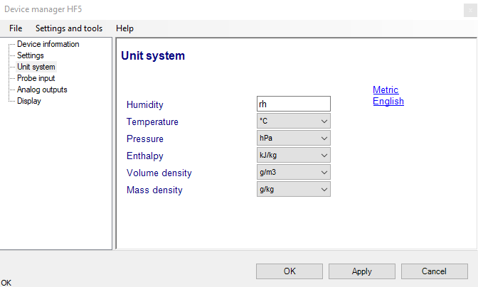
Humidity: enter here the letters to be used after the “%” symbol used for relative humidity
Temperature and other parameters: Left click on the arrow to the right of the text box and select the engineering unit.
Click with the mouse on the blue links labeled Metric or English to globally set the unit system for all parameters.
Note: regarding both HW5 and the transmitter outputs and display, the unit system selected for the transmitter overrides the unit system selected for the probe.
Time Format, Date Format, Date Separator: these settings can be changed to match your preferences practices
Note: For both HW5 and the local HygroLab C1 display, the unit system selected for the HygroLab C1 overrides the unit system selected for the probe.
Display
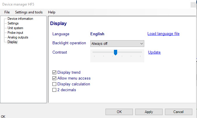
Load Language File: click on this link to change the language of the device internal menu by writing to the transmitter the contents of a language file present on your PC
Backlighting: click on the arrow to the right of the box and select from Always off, Always on or On Key Press
Contrast: use the slider to adjust the contrast of the local LC display and click on the Update link to change the contrast. Click on the Update link to write the new contrast setting to the transmitter.
2 Decimals: check this box to have the display show the values with 2 decimals instead of one decimal
Trend Indicator Stability: enter in this text field the stability criteria used by the trend indicators. A value of 0.01 means that when the rate of signal change is less than 0.01 units per minute, the signal is shown as stable.
Show Trend Indicator: check this box to enable the trend indicators on the optional local display. Trend indication within the HW4 Current Values tab is a Global Setting of HW4 (HW4 Main Menu > Settings and Tools > View tab)
Allow Menu Access: put a check mark in this box to allow access to the internal menu of the HygroLab C1 from the keypad.
Probe Input
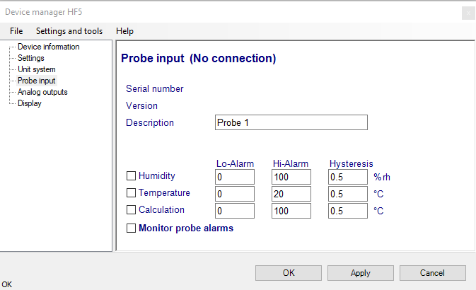
Description: enter here a description for the probe input (maximum 12 characters). This text can be displayed in the HW5 current Values tab.
Lo-Alarm, Hi-Alarm, Hysteresis: alarm conditions can be defined for humidity, temperature and the calculated parameter. Values that are below the low limit value or above the high limit value will trigger a digital alarm (there is no alarm for the analog output signals). The value specified under “hysteresis” is used for both the low and the high limits.
The HW5 will not show an out-of-limits value alarm by using red characters on the monitor screen anymore!
Note: The alarm will be only shown on the display of the device.
Monitor Probe Alarms: When the function is enabled, the device monitors the alarms generated at the probe level such as out-of-limit value and / or bad sensor alarm. When out-of-limit values have been defined both for the device and for the probe, the narrowest set of limits is used to trigger a digital alarm.
AW Mode Settings
Enable Water Activity Mode: check this box to enable the Aw mode. In this mode, both HW5 and the the device automatically display humidity for all probe inputs as Aw (1.00 aw = 100 %RH)
Enable Beeper: when this box is checked, the device gives an acoustic signal during 5 seconds at the end of each Aw measurement
Save Results to Data Bin: when this box is checked, the device automatically saves the water activity value, the temperature value as well as the date and time at the end of each measurement. Probe 1 is always saved to AwBin1, probe 2 to AwBin2, etc. (up to 500 records per probe).
AwQuick Mode Settings: Click on the radio button to select the AwQuick option. This option accelerates the measurement of water activity. With most products the time required to measure water activity is reduced to typically 5 minutes. The measurement starts simultaneously for all probe inputs and is ended automatically.
Settings:
o Dwell Time (minutes): initial time during which the AwQuick algorithm does not run
o Temperature Stability (˚C/ min): defines the temperature stability requirement during the measurement
AwE Option: Click on the radio button to select the AwE option or conventional water activity measurement, the device waits for full equilibration of the measured product. The measurement starts simultaneously for all probe inputs. The HygroLab C1 automatically detects full equilibrium conditions and ends the measurement at that time.
Settings:
o Humidity Stability (aw / min): the measurement ends when this requirement is met.
o Temperature Stability ( ˚C/ min): the measurement carries on as long as this stability requirement is not met
AW Mode Results
When enabled to do so (Aw Mode – Settings) the HygroLab C1 automatically saves the water activity value, the temperature value as well as the date and time at the end of each measurement. Probe 1 is always saved to AwBin1, probe 2 to AwBin2, etc. (up to 500 records per probe).
Use the form shown above to download the contents of any data bin to the HW4 PC in the form of a text file. The following is reported for each measurement: date, time, end result for water activity, temperature at the end of the measurement, method of measurement (AWQ = AwQuick, AWE = conventional measurement).