Overview
This section of the HW5 manual covers only the HW5 functions that are unique to the PF43x digital interface. HW5 functions that are not device dependent are covered in General HW5 feature.
Device Manager
The HW5 functions available for the HygroFlex are illustrated below:
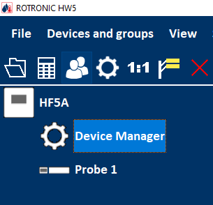
To open the Device manager form, click with the mouse on Device Manager. The Device Manager form is used to configure the HygroFlex and to read device specific information.
When Device Manager is started, it automatically interrogates the device and downloads its current configuration.
Device Information
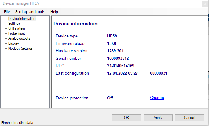
RS485 address: click on the underlined link to change the instrument address to be used in conjunction with an RS-485 network (multi-drop). Each network address should be unique and within the values of 0 to 63.
Note: the default factory RS-485 address is 0. Unless necessary, do not manually modify this address. HW4 will automatically change the RS-485 address of the device, if so required.
Device Protection: for a description of this function, see document General HW5 feature
FORGOT THE PASSWORD? - Power down the device. After powering up the device, you have about one minute to use the default password !resume! (include the exclamation marks). After one minute the default password will be no longer accepted.
The different sub-forms that are available within the Device Manager form are listed in a tree located on the left pane of the form. The number of sub-forms depends on the PF4 model (Device Type). To select a sub-form, click on it with the left mouse button.
Device Manager Menu Bar
The Device Manager menu bar is located at the top of the form.
File
The file menu is used to save to the PC, or to retrieve from the PC, the configuration settings of the device. The settings are saved in an XML file with the extension DAT. Saving the configuration settings to a file is useful for several reasons:
provides a backup when the device configuration has been changed in error
provides a means of quickly configuring a replacement device in the exact same manner as the original device
provides a means of quickly configuring a number of identical devices
Open: opens the device configuration folder specified in HW5 Global Settings - File Locations Tab - and displays all available probe and device configuration files (extension DAT). Select the appropriate file and click on Open in the explorer form. The contents of the configuration file are loaded to the Device Manager form. Review the contents of the Device Manager sub-forms. Click on the Device Manager OK button to write the configuration settings to the device or click on the Cancel button to leave the device unchanged.
Save As: saves the current configuration to an XML file with the extension DAT) in the device configuration folder specified in HW5 Global Settings - File Locations Tab. If so desired, any directory and any file type may be specified.
Tools
Firmware Update: This tool is used to update the firmware of the HF8 after downloading a new firmware file from the ROTRONIC website to your PC. Firmware files are given a name that shows both to which device the file applies and the version number of the firmware. All firmware files have the extension HEX or ROF. The ROTRONIC website will publish firmware updates as required. The tool opens a form that allows you to specify the folder where the firmware update file is located and to select the file. Click on OPEN to start the update process.
IMPORTANT: the device must be powered during the entire process. Loss of power when the transmitter is being updated may have unexpected results and prevent future operation of the device.
Generate Protocol: generates a Device Configuration Protocol. This text file is automatically saved in the folder specified in HW5 Global Settings - File Locations Tab. If so desired, any directory and any file type may be specified. This action is not recorded in the User Event file.
Settings
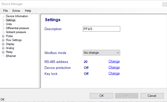
Description: Device Name, as far as possible use a unique device name (maximum 12 characters)
Fixed Pressure Value: enter a value for the fixed barometric pressure value to be used by the PF4 and select the unit for this value (hPa, Inch HG or PSI)
Modbus mode: Only available for the new PF4 generation.
RS-485 address: Click on the underlined blue link to change the RS485 address to be used conjunction with an RS-485 network (multi-drop). Each network address should be unique and within the values of 1 to 64.
Device protection: This function is used to prevent unauthorized access to critical functions such as configuration changes, humidity and temperature adjustment, etc.
Click on the underlined link Change next to “Device protection”. HW4 opens a form named “Enable device protection” if the current device protection status is “Off”. Input a password (max. 8 characters) and confirm with “OK”. The device protection status changes to “On”.
To reverse a Device protection “On” status to “Off”, click Change. A form “Disable device protection” appears, where you input the password and confirm with “OK”. The device protection status changes to “Off”.
Click on the Device Manager OK button to write the new protection settings to the data logger.
Key lock: This function is used to prevent accidental input via the keyboard.
Click on the underlined link Change next to “Key lock”. HW4 opens a form named “Enable Key lock” if the current key lock status is “Off”. Input a password (max. 8 characters) and confirm with “OK”. The Key lock status changes to “On”.
To reverse a Key lock “On” status to “Off”, click Change. A form “Disable Key lock” appears, where you input the password and confirm with “OK”. The Key lock status changes to “Off”.
FORGOT THE PASSWORD? - Power down the probe. After powering up the probe, you have about one minute to use the default password: !resume! (Include the exclamation marks). After one minute, the default password is no longer accepted.
Unit System
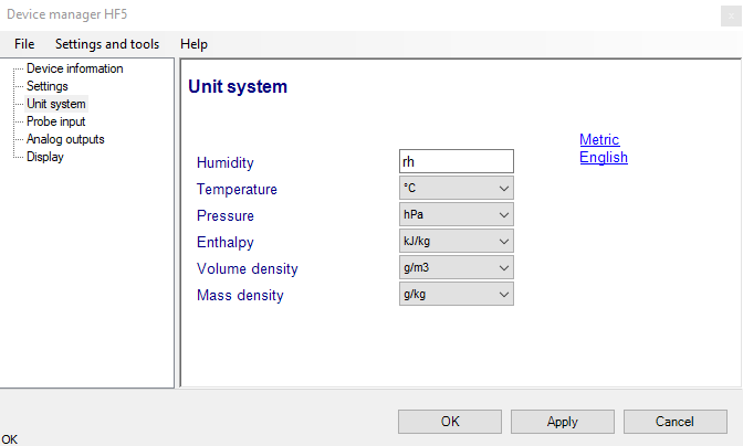
Humidity: enter here the letters to be used after the “%” symbol used for relative humidity
Temperature and other parameters: Left click on the arrow to the right of the text box and select the engineering unit.
Click with the mouse on the blue links labeled Metric or English to globally set the unit system for all parameters.
Note: regarding both HW5 and the transmitter outputs and display, the unit system selected for the transmitter overrides the unit system selected for the probe.
Differential Pressure
Description: Enter a description for this input (maximum 12 characters)
Unit: use the drop down menu to select the unit for differential pressure:
Pa
inH2O
mPSI
mBar
mmHG
mmH2O
Torr
g/cm2
Filter: enter the desired noise filtering level for the differential pressure measurement (0 to 13). The factory default is 0 (no filtering)
Simulation Value: place a mark in the check box to make the PF4 generate a fixed differential pressure value instead of the actual measurement.
The fixed value must be with the following limits: -999.99 and 9999.99
Note: Make sure that the fixed value falls within the range specified for the PF4 analog outputs
Using the PF4 as a simulator serves the purpose of verifying the analog signal transmission (loop validation) after completing an installation.
Alarm: use the mouse to check or uncheck the box labeled Alarm. When the alarm function is enabled, the PF4 generates an alarm when measurements are outside of the range defined by the Lo-Alarm and Hi-Alarm values.
Note: The alarm will be only shown on the display not in the HW5 anymore.
PT100
Description: Enter a description for this input (maximum 12 characters).
Unit: use the drop down menu to select the temperature unit (°C / °F)
Simulation Value: place a mark in the check box to make the PF4 generate a fixed temperature value instead of the actual measurement.
The fixed value must be with the following limits: -999.99 and 9999.99 Note: Make sure that the fixed value falls within the range specified for the PF4 analog outputs
Using the PF4 as a simulator serves the purpose of verifying the analog signal transmission (loop validation) after completing an installation.
Alarm: use the mouse to check or uncheck the box labeled Alarm. When the alarm function is enabled, the PF4 generates an alarm when measurements are outside of the range defined by the Lo-Alarm and Hi-Alarm values.
HC2 probe
Probe Input
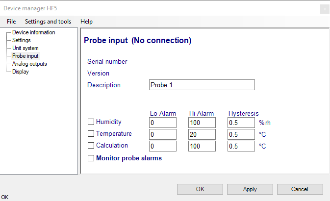
Description: enter here a description for the probe input (maximum 12 characters). This text can be displayed in the HW5 current Values tab.
Lo-Alarm, Hi-Alarm, Hysteresis: alarm conditions can be defined for humidity, temperature and the calculated parameter. Values that are below the low limit value or above the high limit value will trigger a digital alarm (there is no alarm for the analog output signals). The value specified under “hysteresis” is used for both the low and the high limits.
The HW5 will not show an out-of-limits value alarm by using red characters on the monitor screen anymore!
Note: The alarm will be only shown on the display of the device.
Monitor Probe Alarms: When the function is enabled, the device monitors the alarms generated at the probe level such as out-of-limit value and / or bad sensor alarm. When out-of-limit values have been defined both for the device and for the probe, the narrowest set of limits is used to trigger a digital alarm.
Calculation: based on the signals from the HC2 probe, the PF4 can perform psychrometric calculations.
Analog Input / Output
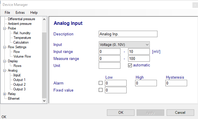
Description: Enter a description for this input (maximum 12 characters).
Input: Left click on the arrow to the right of the text box and select the preferred input.
Input range & measure range: Enter here the letters to be used for the specific range.
Unit: Enter here the letters to be used. Use the mouse to check or uncheck the box labeled automatic.
Alarm: Use the mouse to check or uncheck the box labeled alarm. When the alarm function is enabled, the PF4/5 generates an alarm when measurements are outside of the range defined by the low alarm and high alarm values. A limit alarm can be displayed on the display.
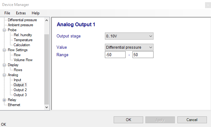
Depend on the device variation the PF4 can have one or two or three analog outputs to be set.
Output stage: Left click on the arrow to the right of the text box and select the preferred input.
Value: Left click on the arrow to the right of the text box and select the preferred parameter.
Range: Enter here the letters to be used for the range.
Load: Enter here the letters to be used for the load.
Display (optional)
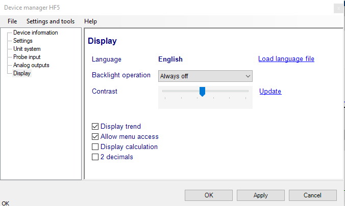
Load Language File: click on this link to change the language of the device internal menu by writing to the transmitter the contents of a language file present on your PC
Backlighting: click on the arrow to the right of the box and select from Always off, Always on or On Key Press
Contrast: use the slider to adjust the contrast of the local LC display and click on the Update link to change the contrast. Click on the Update link to write the new contrast setting to the transmitter.
Enable Trend: check this box to enable the trend indicators on the optional local display. Trend indication in the HW5 Current Values tab is a Global Setting of HW5 (HW5 Main Menu > Settings and Tools > View tab)
Allow Menu Access: this box applies only for models that have a local display and keypad and is used to prevent access to the internal menu of the transmitter.
Display Calculation: check this box to have the display show by default relative humidity, temperature and the calculated parameter.
2 Decimals: check this box to have the display show the values with 2 decimals instead of one decimal
Line 1 / Line 2 / Line 3: The display of the PF4 can show up to 3 lines corresponding to up to 3 parameters. Select the parameter to be shown on each line of the display by selecting it from the drop down list. The available options depend on the PF4 model. Any line can also be disabled.
Relay
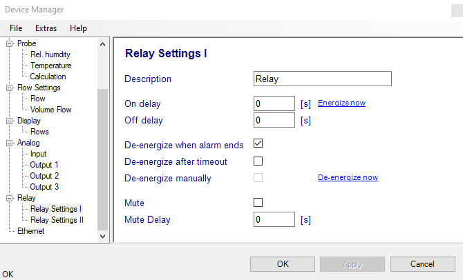
Description: Enter a description for this input (maximum 12 characters). It appears on the chart as the name of the relay.
On delay: Use this field to specify the amount of time during which the alarm must be on before the relay is energized.
Off delay: Use this field to specify the amount of time during which the alarm must be off before the relay switches off.
Energize now: Click on the link to energize the switch immediately. It is for testing for the system integration.
De-energize now: Click on the link to de-energize the switch immediately. It is for testing for the system integration.