Overview
This section of the HW5 manual covers only the HW4 functions that are unique to the HF3/4 digital interface. HW5 functions that are not device dependent are covered in General HW5 feature.
Device Manager
The device manager can be opened for any device in the device tree.
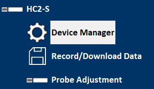
A click opens the following dialog box
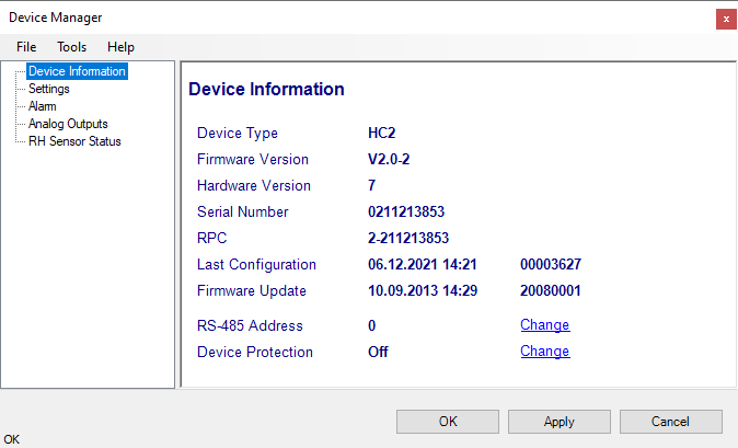
Typically, several device properties and settings are displayed and can be set. This information and settings differ from device to device type.
•Device information
•Settings (name, measurement units, fix values etc.)
•Device Manager of the connected probe
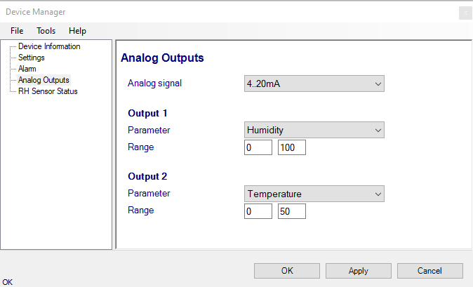
•Analog Inputs and outputs (range and scaling)
•Digital Inputs
•Relay
•Ethernet settings
•etc.
For detailed information, please see chapter Devices
Note •Alarm settings can be set in the device, but are not displayed / supported by the HW5 anymore. |
FORGOT THE PASSWORD? - Power down the device. After powering up the device, you have about one minute to use the default password !resume! (include the exclamation marks). After one minute the default password will be no longer accepted.
Settings
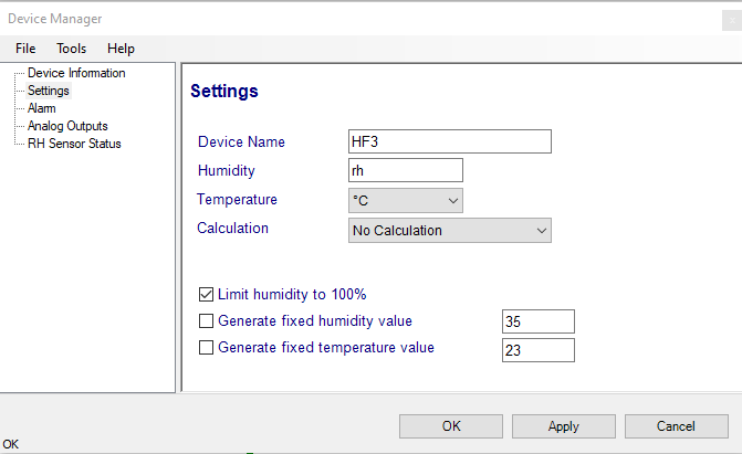
Device name: As far as possible use a unique device name (maximum 12 characters).
Humidity: Possibility to change the abbreviation of the relative humidity, which is different in other languages.
Note: It can only have max. 2 digits
Temperature: Changing the unit of the Temperature from Celsius to Fahrenheit.
Calculation: Adding a third parameter. Dew point (Dp), Frost point (Fp) etc. (depends on the device).
Limit humidity to 100%: typically, the humidity sensor gives a reading slightly above 100 %RH when condensation occurs at the surface of the sensor. Check this box to limit the maximum value of humidity to 100 %RH.
Generate fixed humidity/temperature value: place a check mark in these boxes to make the HygroFlex generate fixed humidity and temperature values instead of the actual measurements.
The fixed values must be with the following limits: -999.99 and 9999.99.
Note: Make sure that the fixed values fall within the range specified for the HygroFlex analog outputs. Using the device as a simulator serves the purpose of verifying the analog signal transmission (loop validation) after completing an installation.
Alarm
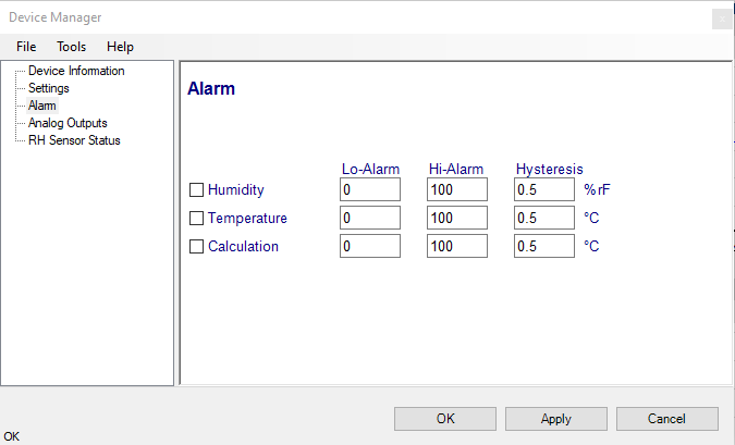
Note: This function has no effect on the device analog outputs and applies only to the transmitter optional display (an alarm symbol appears). The digital communication with a PC via service connector or permanent digital interface will not work anymore with the HW5.
Alarm conditions can be defined for humidity, temperature and the calculated parameter. Values that are below the low alarm value or above the high alarm value will trigger an alarm. The value specified for the alarm function hysteresis is used for both the low and the high alarm.
All versions of HW5 will show an out-of-limits value alarm in red on the monitor screen. In addition, HW4 Professional can be configured (HW5 global settings - Alarm settings tab) to display an alarm table and generate a report whenever an out-of-limits condition occurs.