Accessing HL-20D
Connect the mini USB socket on the Back of HL-20 or HL-21 by means of a Rotronic service cable AC3006 (UART = USB) to an USB port of the PC, where HW5 is installed. Make sure that the correct Rotronic USB driver is installed. If this is the case a window opens, which informs you that a new device [HL-20] was found.
Initial Configuration
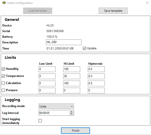
General
Here you get some general information on the device like Device type, Serial Number, Battery capacity, and time. The field “Description” is filled in by default with “Rotronic”. You may change it to a meaningful word with 8 characters max. like “Office-1”. Checkmark “Update” for an automatic synchronization with the HW5 date and time.
Limits
Here you may change preset values for Low and High Limits and Hysteresis of Humidity and Temperature and switch the monitoring of these values on or off.
Logging
Decide whether the Logging Mode is “Loop” (if the memory is full the oldest logs are overwritten by the new log values) or “Stop if full”. Select the Logging interval between 5 seconds and 1 hour in 1-sec-increments. Checkmark “Start logging immediately” to start logging immediately when the wizard is completed. Set a checkmark in the “Lock start/stop key” box to lock the key labeled START/STOP in the front plate of the logger.
A click on “Save template” saves the current configuration data to HW5, “Load template” retrieves them and overwrites the respective entries in the form. This is especially useful to configure a great many of loggers with identical parameters.
Press “Finish” and the entries will be written to the logger.
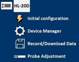
When the initial configuration was successful. Click on the + sign to the left of the icon to expand the device tree. Thereby a list of the available function modules is displayed: “Initial configuration”, “Device Manager”, “Record/Download Data” and “Probe Adjustment”.
Alternative: If the device is not automatically recognized, you may access it as described consecutively.
Open HW5 and click “Devices and groups” followed by “Add device”.
Select “HL20” from the device type list and choose “USB” from the “PC interface” list.
Confirm by clicking on “OK” the configuration wizard starts.
Device Manager
Device Information
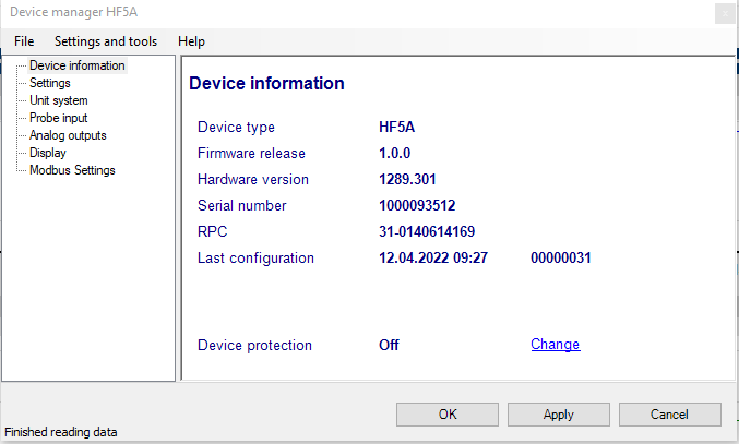
RS485 address: click on the underlined link to change the instrument address to be used in conjunction with an RS-485 network (multi-drop). Each network address should be unique and within the values of 0 to 63.
Note: the default factory RS-485 address is 0. Unless necessary, do not manually modify this address. HW4 will automatically change the RS-485 address of the device, if so required.
Device Protection: for a description of this function, see document General HW5 feature
FORGOT THE PASSWORD? - Power down the device. After powering up the device, you have about one minute to use the default password !resume! (include the exclamation marks). After one minute the default password will be no longer accepted.
Device Manager Menu Bar
The Device Manager menu bar is located at the top of the form.
File
The file menu is used to save to the PC, or to retrieve from the PC, the configuration settings of the device. The settings are saved in an XML file with the extension DAT. Saving the configuration settings to a file is useful for several reasons:
•provides a backup when the device configuration has been changed in error
•provides a means of quickly configuring a replacement device in the exact same manner as the original device
•provides a means of quickly configuring a number of identical devices
Open: opens the device configuration folder specified in HW5 Global Settings - File Locations Tab - and displays all available probe and device configuration files (extension DAT). Select the appropriate file and click on Open in the explorer form. The contents of the configuration file are loaded to the Device Manager form. Review the contents of the Device Manager sub-forms. Click on the Device Manager OK button to write the configuration settings to the device or click on the Cancel button to leave the device unchanged.
Save As: saves the current configuration to an XML file with the extension DAT) in the device configuration folder specified in HW5 Global Settings - File Locations Tab. If so desired, any directory and any file type may be specified.
Tools
Firmware Update: This tool is used to update the firmware of the device after downloading a new firmware file from the ROTRONIC website to your PC. Firmware files are given a name that shows both to which device the file applies and the version number of the firmware. All firmware files have the extension HEX or ROF. The ROTRONIC website will publish firmware updates as required. The tool opens a form that allows you to specify the folder where the firmware update file is located and to select the file. Click on OPEN to start the update process.
IMPORTANT: the device must be powered during the entire process. Loss of power when the transmitter is being updated may have unexpected results and prevent future operation of the HygroLab C1.
Generate Protocol: generates a Device Configuration Protocol. This text file is automatically saved in the folder specified in HW5 Global Settings - File Locations Tab. If so desired, any directory and any file type may be specified. This action is not recorded in the User Event file.
Settings
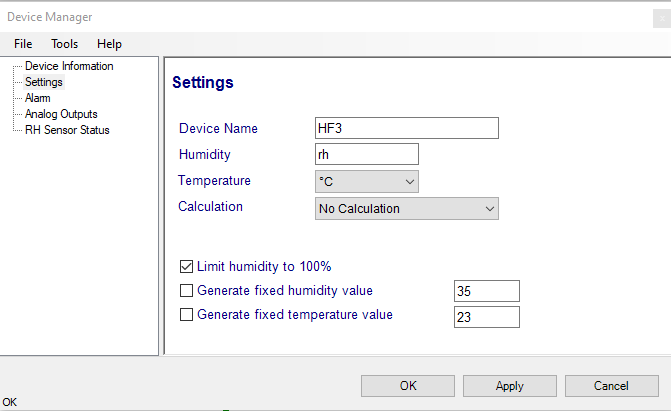
Device name: As far as possible use a unique device name (maximum 12 characters).
Humidity: Possibility to change the abbreviation of the relative humidity, which is different in other languages.
Note: It can only have max. 2 digits
Temperature: Changing the unit of the Temperature from Celsius to Fahrenheit.
Calculation: Adding a third parameter. Dew point (Dp), Frost point (Fp) etc. (depends on the device).
Limit humidity to 100%: typically, the humidity sensor gives a reading slightly above 100 %RH when condensation occurs at the surface of the sensor. Check this box to limit the maximum value of humidity to 100 %RH.
Generate fixed humidity/temperature value: place a check mark in these boxes to make the HygroFlex generate fixed humidity and temperature values instead of the actual measurements.
The fixed values must be with the following limits: -999.99 and 9999.99.
Note: Make sure that the fixed values fall within the range specified for the HygroFlex analog outputs. Using the device as a simulator serves the purpose of verifying the analog signal transmission (loop validation) after completing an installation.
Alarm
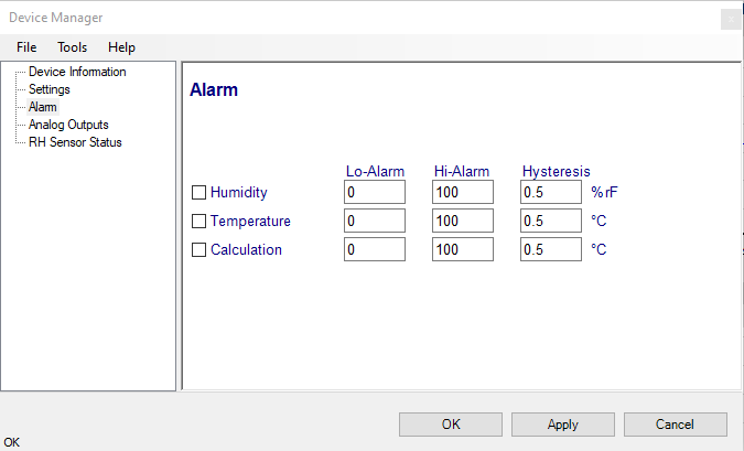
Note: This function has no effect on the device analog outputs and applies only to the transmitter optional display (an alarm symbol appears). The digital communication with a PC via service connector or permanent digital interface will not work anymore with the HW5.
Alarm conditions can be defined for humidity, temperature and the calculated parameter. Values that are below the low alarm value or above the high alarm value will trigger an alarm. The value specified for the alarm function hysteresis is used for both the low and the high alarm.
All versions of HW5 will show an out-of-limits value alarm in red on the monitor screen. In addition, HW5 can be configured (HW5 global settings - Alarm settings tab) to display an alarm table and generate a report whenever an out-of-limits condition occurs.
Display (optional)
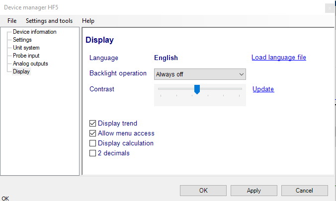
Load Language File: click on this link to change the language of the device internal menu by writing to the transmitter the contents of a language file present on your PC
Backlighting: click on the arrow to the right of the box and select from Always off, Always on or On Key Press
Contrast: use the slider to adjust the contrast of the local LC display and click on the Update link to change the contrast. Click on the Update link to write the new contrast setting to the transmitter.
Enable Trend: check this box to enable the trend indicators on the optional local display. Trend indication in the HW5 Current Values tab is a Global Setting of HW5 (HW5 Main Menu > Settings and Tools > View tab)
Allow Menu Access: this box applies only for models that have a local display and keypad and is used to prevent access to the internal menu of the transmitter.
Display Calculation: check this box to have the display show by default relative humidity, temperature and the calculated parameter.
2 Decimals: check this box to have the display show the values with 2 decimals instead of one decimal
Turn-Off after: this setting is used to enable or disable the display sleep function. Click on the arrow to the right of the box and select from Never (the display can still be turned off manually with the function key), After 1 minute, After 5 minutes, After 10 minutes or After 20 minutes (the display is automatically turned off). Turning off the display as soon as practically possible is essential to conserve battery power.
Data Recording
Data Recording is used to configure the data recording functions of the device, to start and stop data logging by the device and to download the recorded data to the HW5 PC.
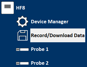
To select Data Recording, click on it with the left mouse button. HW5 opens the Data Recording form.
Data logging - Settings
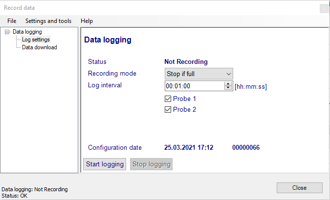
This form is used to select the following:
o Recording mode:
- Stop if full: ends the recording when the memory is full
- Loop: when the memory is full, keep recording and dump the oldest data record
o Log interval: 5 seconds to 1 hour, in 5 seconds increments
Note: starting or stopping data recording with HW5 automatically sets the data logger real time clock to the PC date and time.
Data Logginig - Data Download
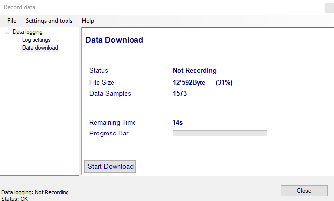
This form is used to download to the PC the data present in the data logger memory. The file can be downloaded even when data is still being recorded.
Notes:
•The file format (text file - .txt or binary - .log) used by HW4 when saving the data to disk can be configured from the menu bar of the Data Logging form: Settings and Tools > Log File Format
•HW5 can print a protocol of the Data Logging settings: Settings and Tools > Generate Protocol
Click on the blue link labeled “Download Data” to download and view the recorded data.