This section provides detailed instructions on how to properly connect the TF5A device to power sources and other necessary components. It covers all possible wiring options. Proper attention to these steps is essential to guarantee reliable and safe functionality of the device.
Standard Transmitter Variants
There are 3 different transmitter variants available, each available with or without display and with 3 different temperature scaling:
Standard Variants / Order Code |
Description |
Output |
TF5A-21D0010100000 |
2-wire with Display |
Analog: 4...20 mA |
TF5A-21X0010100000 |
2-wire without Display |
|
TF5A-21D0010400000 |
2-wire with Display |
|
TF5A-21X0010400000 |
2-wire without Display |
|
TF5A-21D0010200000 |
2-wire with Display |
|
TF5A-21X0010200000 |
2-wire without Display |
|
TF5A-31D0010100000 |
3-/4-wire with Display |
Analog: 4...20 mA |
TF5A-31X0010100000 |
3-/4-wire without Display |
|
TF5A-31D0010400000 |
3-/4-wire with Display |
|
TF5A-31X0010400000 |
3-/4-wire without Display |
|
TF5A-31D0010200000 |
3-/4-wire with Display |
|
TF5A-31X0010200000 |
3-/4-wire without Display |
|
TF5A-D1D0010100000 |
3-/4-wire with Display |
Analog: 4...20 mA
Digital: Modbus RTU |
TF5A-D1X0010100000 |
3-/4-wire without Display |
|
TF5A-D1D0010400000 |
3-/4-wire with Display |
|
TF5A-D1X0010400000 |
3-/4-wire without Display |
|
TF5A-D1D0010200000 |
3-/4-wire with Display |
|
TF5A-D1X0010200000 |
3-/4-wire without Display |
Wiring Diagram
TF5A-2: (2-wire option)
Terminal Overview |
Analog Terminal Description |
|
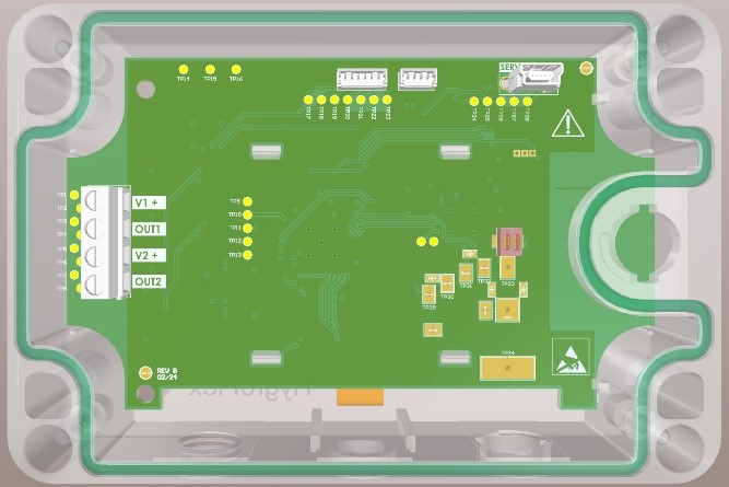 |
V1+
OUT1
V2+
OUT2 |
Power Supply +
Analog Output 1
Power Supply +
Analog Output 2 |
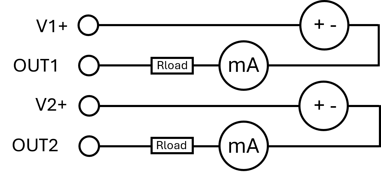
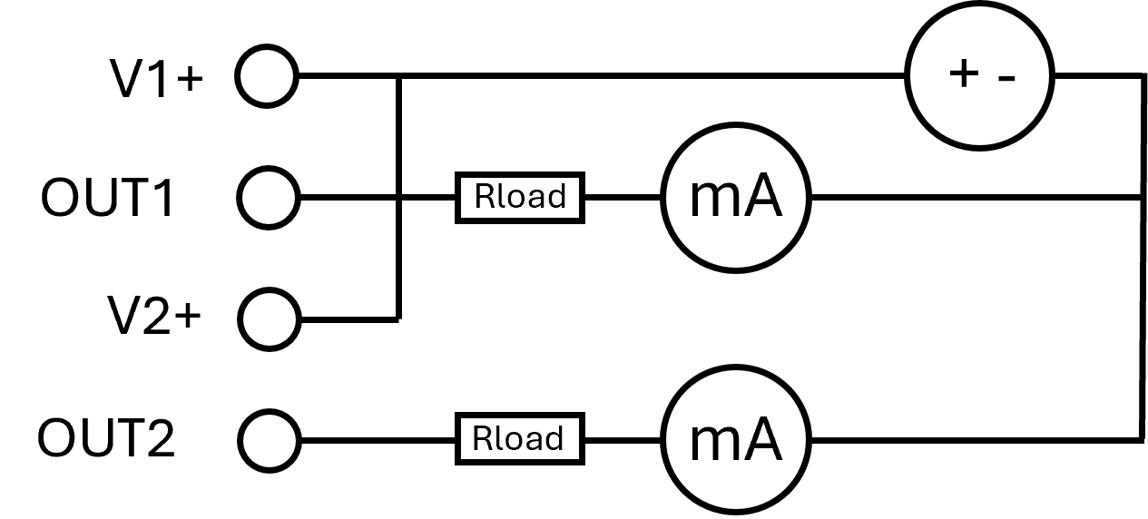
Connection diagram |
||
Two separated power supply |
One power supply |
|
 |
 |
|
Note: The service cable AC3009 must not be connected simultaneously with the power supply.
TF5A-3 / TF5A-D: (3-wire option)
Terminal Overview |
Analog Terminal Description |
|
 |
V+
V-
OUT1+
OUT1-
OUT2+
OUT2- |
Power Supply +
Power Supply -
Analog output 1+
Analog output 1-
Analog output 2+
Analog output 2- |
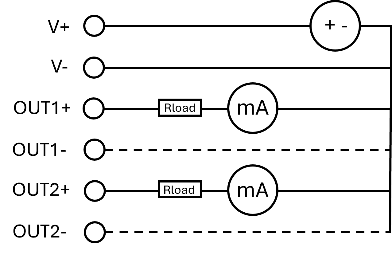
Connection diagram |
||
Current |
Voltage |
|
 |
 |
|
Note: The service cable AC3009 must be used in case that the power supply is simultaneously connected.
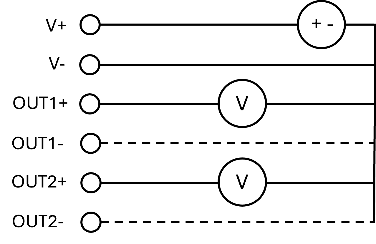
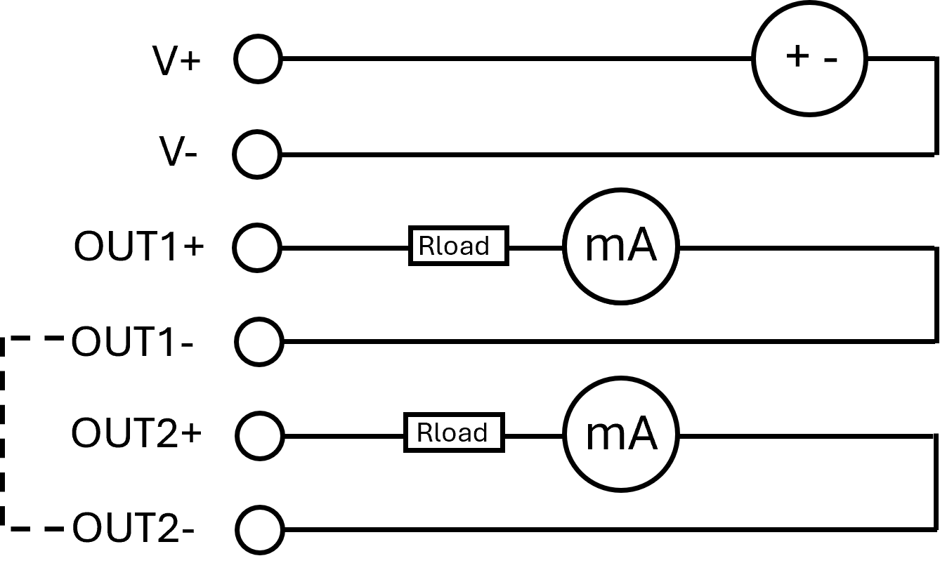
TF5A-3 / TF5A-D: (4-wire option)
Terminal Overview |
Analog Terminal Description |
|
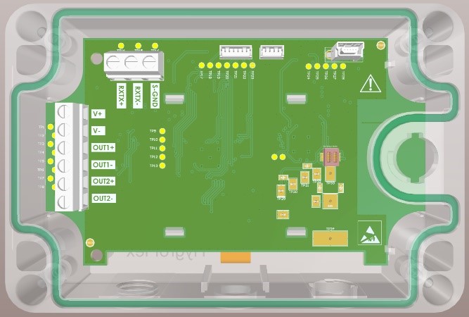 |
V+
V-
OUT1+
OUT1-
OUT2+
OUT2- |
Power Supply +
Power Supply -
Analog output 1+
Analog output 1-
Analog output 2+
Analog output 2- |
Digital Terminal Description |
||
RXTX+
RXTX-
S-GND |
RS485+ (A)
RS485- (B)
Signal Ground (-) |
|
Connection diagram |
||
Current |
Voltage |
|
 |
 |
|
Note: The service cable AC3009 must be used in case that the power supply is simultaneously connected.
Attention: The temperature transmitter devices must only be contacted as described above!