Output Monitoring Mode
Error messages of 3/4-wire Transmitter:
Variants |
Description |
Output |
HF5A-31D0300210100 |
3-/4-wire with Display |
Analog 0(4)...20 mA, 0...5(10) V |
HF5A-31X0000210100 |
3-/4-wire without Display |
Analog 0(4)...20 mA, 0...5(10) V |
HF5A-D1D0300210100 |
3-/4-wire with Display |
Analog 0(4)...20 mA, 0...5(10) V & Digital Modbus RTU |
HF5A-D1X0300210100 |
3-/4-wire without Display |
Analog 0(4)...20 mA, 0...5(10) V & Digital Modbus RTU |
Connection Diagram
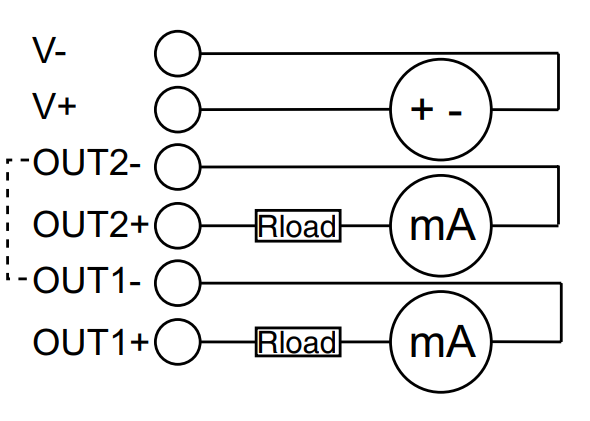
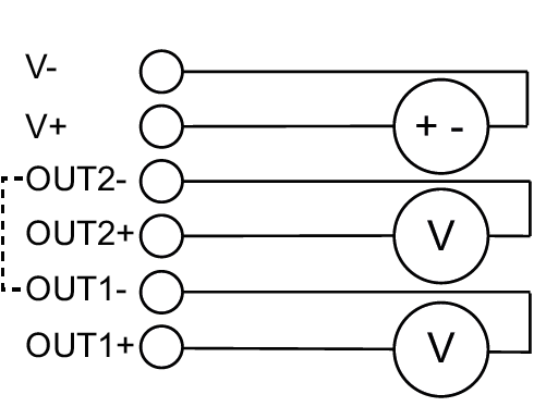
3-wire HF5A-31 & HF5A-D1 / 4-wire HF5A-31 & HF5A-D1:
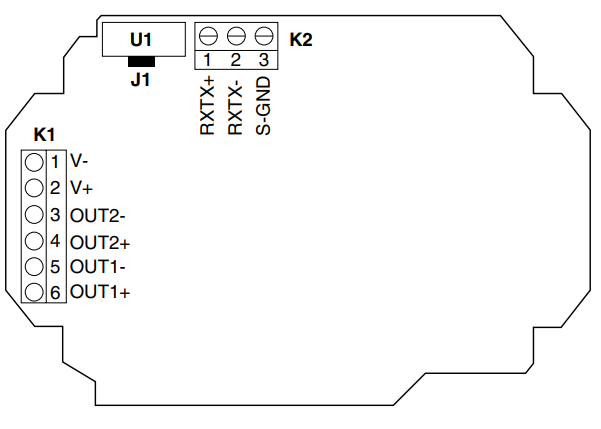
Terminal Overview |
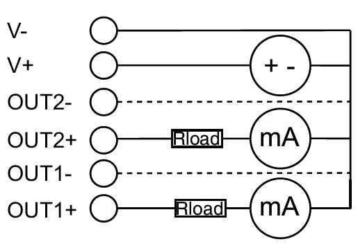
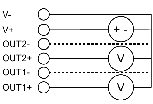
Connection diagram |
|
3-wire (J1 mounted) |
Current |
Voltage |
|
|
|
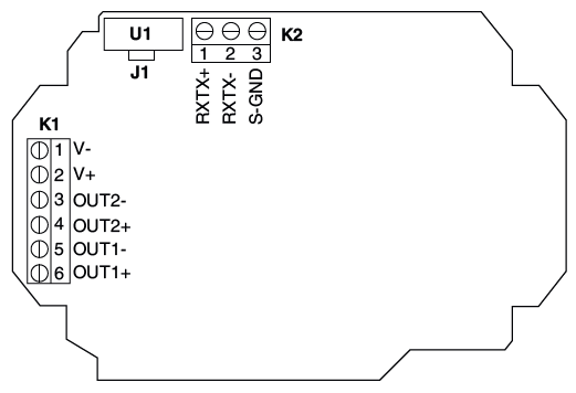
Terminal Overview |
Connection diagram |
|
4-wire (J1 unmounted) |
Current |
Voltage |
|
|
|
Terminal |
Description |
K1-1-V- |
Power Supply - |
K1-2-V+ |
Power Supply + |
K1-3-OUT2- |
Analog output 2- |
K1-4-OUT2+ |
Analog output 2+ |
K1-5-OUT1- |
Analog output 1- |
K1-6-OUT1+ |
Analog output 1+ |
Note: Recommendation of Rotronic - 4 - wire galvanic separated with unmounted Jumper J1 - with the benefit that the power supply and the outputs are
separated galvanic isolated. Per default, the Jumper J1 is mounted.
In order to get the normal operation status Green, the following errors have to be resolved:
Output Monitoring current:

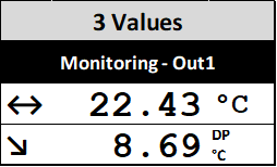
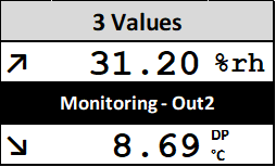
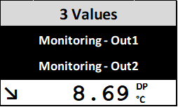
To prevent an error message within the current Output Monitoring, the current version should have at least a 100 Ohm Resistor applied to the OUT1+ and OUT1-,
respective OUT2+ and OUT2-.
In order to maintain an error free operation, either the analogue Outputs must have a load or the Analog Outputs are programmed with HygroSoft to Unused.
Load
Type |
Power supply |
Load |
Output |
2-wire |
|||
HF5A-21 |
18...36 VDC |
Max. 500 Ω |
4...20 mA |
3- / 4-wire |
|||
HF5A-31 |
18...36 VDC |
Max. 500 Ω |
4...20 mA |
0...20 mA |
|||
Min. 10 kΩ |
0...5 V |
||
0...10 V |
|||
HF5A-D1 |
Max. 500 Ω |
4...20 mA |
|
0...20 mA |
|||
Min. 10 kΩ |
0...5 V |
||
0...10 V |
|||
- |
Digital RS485 |
||
Output Monitoring voltage:


To prevent an error message within the voltage Output Monitoring, the voltage version should have at least a 10kOhm Resistor applied to the OUT1+ and OUT1-, respective OUT2+ and OUT2-.
In order to maintain an error free operation, either the analogue Outputs must have a load or the Analog Outputs are programmed with HygroSoft to Unused.
