This short guidance explains how to connect the RMS-HCD-S to a computer and read out and understand the MODBUS RTU protocol.
Material list:
•RMS-HCD probe (delivery a MODBUS RTU over UART protocol).
•AC3001 (converts UART to USB).
•E2-05XX-MODBUS (converts UART to RS485):
•US-RS485-WE-1800-BT (RS485 to USB converter: Third party device, not supplied by Rotronic). The E2-05XX-MODBUS and the US-RS485-WE-1800-BT need to be connected together based upon the connection diagram of both devices.
•A MODBUS master software (Third party software, not supplied by Rotronic).
•A Hex to Floating point converter (Third party software, not supplied by Rotronic).
Step 1 |
Review the RMS-HCD MODBUS address of the RMS-HCD probe with the RMS-CONFIG software. Plug the RMS-HCD into the AC3001 probe and add a local Device. |
Step 2 |
Check the MODBUS address under the Info of the Device Settings. The default address is 247: 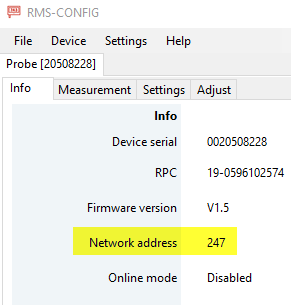 |
Step 3 |
We recommend setting the probe into simulator mode to simplify reading out the data. This is done under the RMS-CONFIG Settings. For this example, we have set a fixed value of 35.12%rh. |
Step 4 |
Plug the RMS-HCD into the E2-05XX-MODBUS/US-RS485-WE-1800-BT combination. Plug the setup into a USB port. |
Step 5 |
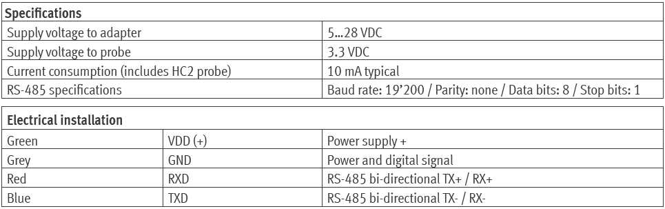
Open up the MODBUS master software tool and input the following details: •Modbus RTU. •Baudrate: 19200. •Parity: None. •Data bits 8. •Stop bits 1. •Slave ID 247.
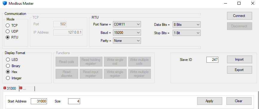 The port name will depend on the computer/port being used. |
Step 6 |
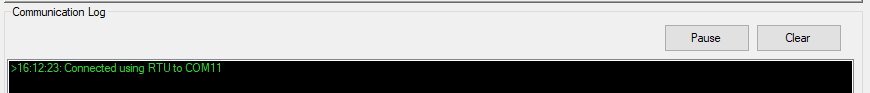
Press connect, the communication log will show if the connection was successful: |
Step 7 |
The MODBUS address overview can be reviewed here: MODBUS. The addresses 31000 and 31001 are the humidity values (RS485 Address is the Register address -1): 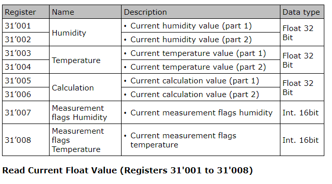 |
Step 8 |
Under the MODBUS Master software, add the start address 31000 and size 4 and press "Apply", then press "Read input register": 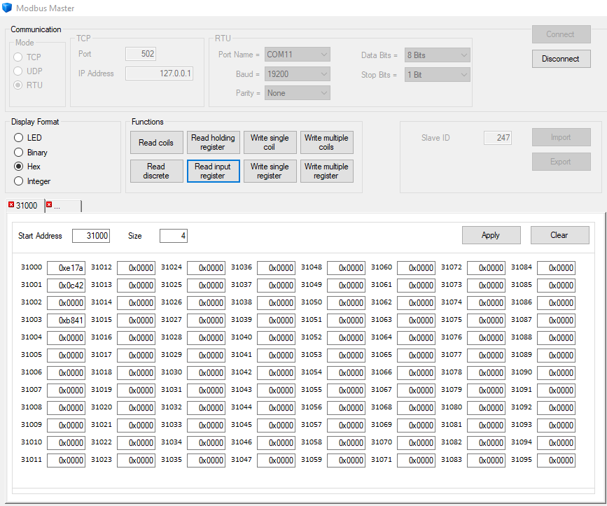 The data received: •31000: 0xe17a •31001: 0x0c42 |
Step 9 |
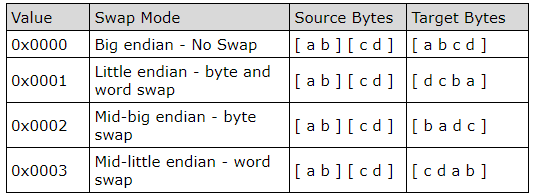
Swap format: the standard setting is 0x0001 with target bytes d c b a:
As the target bytes are d c b a, the hex value is 42 0c 7a e1. |
Step 10 |
In order to calculate the decimal value, the hex to floating point converter is required. We have used an online tool: 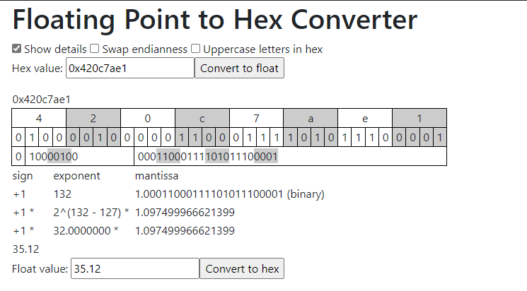 The float value gives us 35.12, which corresponds to the 35.12%rh simulator mode that has been applied. |
Step 11 |
It is possible to change the swap format if required: •Start address: 40001 •Size: 1 •Address: 4001 Type in 0000 for Target bytes a b c d •Press "Apply" •Press "Write single register" 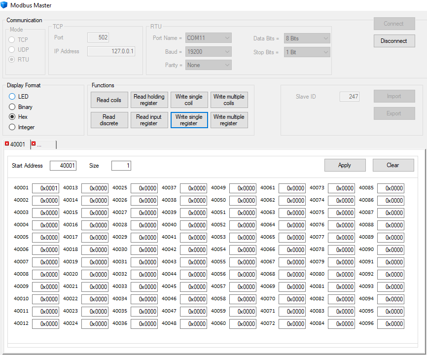 |
Step 12 |
Read humidity values again: 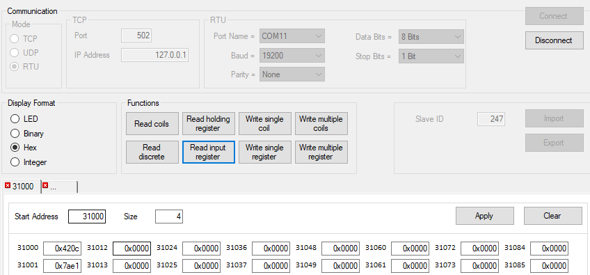 The data received: •31000: 0x420c •31001: 0x7ae1 |
Step 13 |
Swap format: the standard setting is 0x0000 with target bytes a b c d:
As the target bytes are a b c d, the hex value is 42 0c 7a e1. |
Step 14 |
Check again with the calculator: 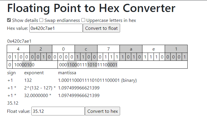 The float value gives us 35.12, which corresponds to the 35.12%rh simulator mode that has been applied. |