HF5 analog outputs
Use the HW5 or HygroSoft software to configure the analog outputs of the HF5 as desired, complete the mechanical and electrical installation, connect the probe and simply power up the HF5.
HF5 digital outputs
The digital outputs of the HF5 use the standard RO-ASCII protocol and do not offer any other option. Users who wish to read the measurement data without the HW5 or HygroSoft software should consult ROTRONIC.
The different types of digital interface available with the HF5 are best used with a PC with the HW5 or HygroSoft software installed. In principle, users should be able to use communication software other than provided from ROTRONIC to read measurement data from the HF5. In this case, communication is limited to the RDD (data request) and REN (RS-485 address change) commands described separately in document Communication Protocol Options (E-M-AC3000-CP).
IMPORTANT: Depending on the type of digital interface, either the PC or the HF5 must be configured by the user as indicated below.
RS-485 serial interface (multi-drop)
Instructions for using the HF5 with a RS-485 network are provided in the following manuals: E-DV04-RS485.01.
Notes:
•Instruments connected to the same RS-485 network must use the same baud rate and each instrument must be given a unique RS-485 address (the address requirement applies to the HF5 but not to its probe)
•RS-485 Compatibility: The communications protocol used by the HF5 is the RO-ASCII protocol. This protocol is not compatible with the protocol used by the previous generation of ROTRONIC products. Do not connect legacy products and the HF5 to the same RS-485 multi-drop network.
The specifications of the RS-485 interface are as follows:
Baud rate :19200
Parity :none
Data bits :8
Stop bits :1
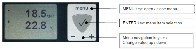
Display and keypad option
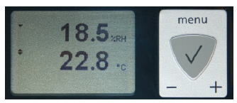
Except for the HF52 (2-wire circuit type), the LC display of the HF5 has a backlight.
The upper line corresponds to relative humidity the bottom line corresponds to temperature.
If enabled the third line corresponds to the calculated Parameter.
The display can be configured to show a trend indicator on each line:
▲: increasing value
▼: decreasing value
In the event of an alarm the display shows the symbol [ ! ] to the right of the value.
For instructions about configuring the display, see the HW5 or HygroSoft manual.
Internal menu (optional keypad and display)
Note: Unauthorized access to the menu can be prevented by disabling the “display menu” setting (use the HygroSoft)
Model HF52 (2-wire circuit type):
Main Menu |
Menu Items |
Selections / Information |
Notes |
Device Settings |
Units |
Metric / English |
|
Contrast |
LC display contrast adjustment |
||
Trend |
On / Off |
Trend indication on the display |
|
Device Information |
Version |
Firmware version |
|
Serial Nbr |
Serial number |
||
Address |
RS-485 address |
||
Type |
Device type |
||
Name |
Device name |
User defined |
|
Probe Information |
Version |
Firmware version |
|
Serial Nbr |
Serial number |
||
Address |
RS-485 address |
||
Name |
Device name |
User defined |
Other HF5 models:
Main Menu |
Menu Items |
Selections / Information |
Notes |
Device Settings |
Units |
Metric / English |
|
Back Light |
Key Press / On / Off |
Display backlight mode |
|
Contrast |
LC display contrast adjustment |
||
Trend |
On / Off |
Trend indication on the display |
|
Device Information |
Version |
Firmware version |
|
Serial Nbr |
Serial number |
||
Address |
RS-485 address |
||
Type |
Device type |
||
Name |
Device name |
User defined |
|
Probe Information |
Version |
Firmware version |
|
Serial Nbr |
Serial number |
||
Address |
RS-485 address |
||
Name |
Device name |
User defined |
|
SensorTest |
Humidity sensor status |
Off / Good / SQ-Tuned / Bad |
|
Record |
On / Off |
Data recording by the probe (max. 2000 values) |
|
Humidity Adjust |
RefValue |
Humidity reference value |
± 0.1 %RH steps |
Acquired |
Number of cal. points in probe memory |
||
<Acquire> |
Save cal. point to probe memory |
||
<Delete> |
Erases all calibration points |
||
<Adjust> |
Effect depends on number of calibration points |
||
Temperature Adjust |
RefValue |
Temperature reference value |
± 0.1 ˚C steps |
<Adjust> |
1-point adjustment only (offset) |
•Record: both the recording mode (start / stop and the log interval cannot be changed from the menu and are as configured with the ROTRONIC HW5 or HygroSoft software.
•SensorTest: Off means that the humidity sensor has not been tested due to the configuration settings of the test. For a description of the automatic humidity sensor test and drift compensation (SQ-tuning) see documents Description and Main Functions (E-T-AC3000-DF-V1).
Displayed parameters (optional keypad and display)
When the menu is not active, press the ENTER key to change which parameters are shown on the display:
•Relative humidity and temperature
•Relative humidity , temperature and calculated parameter (when the calculated parameter is enabled)