The safety of the installed system, where the device is integrated, is the responsibility of the builder of the system.
General wiring guidelines
Power supply wiring
Heavy machinery and instrumentation should not share the same power supply wiring. If this cannot be avoided, noise filters and surge protectors should be used. Most UPS devices have those features already integrated.
Electrical Safety Warning (HF56x)
The HF5 transmitter series includes models designed to operate with a supply voltage of 100…240 VAC. For safety reasons, the electrical installation of these models must be designed providing an adequate protection. A form of an external circuit breaker, switch, fuse or other can be used to separate the transmitter from the supply voltage. Appropriate safety warnings and instructions must be located by the transmitter in order to prevent electrical shock with open transmitter enclosure.
The guarantee of the security of the whole system which includes the HF5 is the responsibility of the
developer of the system.
Ensure that the cable gland is tightened so that this is not detachable by hand.
The electrical installation of the device must be performed by a qualified electrician and correspond with IEC (International Electrotechnical Commission) requirements.
It is important to ensure, to use a suitable mains cable:
•Voltage Range min. 240 VAC
•Cable cross-section : 6 ... 8 mm
•Max Wire cross : 2.5 mm2
•Recommended : 3x075mm2 H05VV-F Cable
•Specify torque: 3-5 Nm
General guidelines for signal cables
The following guidelines are derived from International Standard IEC 61158 / IEC 61784 for the transmission of signals by copper wires. When planning an installation, the rules provided by IEC 61158 / IEC 61784should be followed under consideration of local circumstances to determine the position of machines and equipment.
Whenever the level of electromagnetic interference is expected to be high, both the instruments and signal cables should be placed as far away as possible from the source of interference.
In general, signal cables should be installed in bundles or channels / conduits, separate from other cables as
indicated in the table below:
•Bus signals such as RS485 •Data signals for PCs, printers etc. •shielded analog inputs •unshielded direct current (<= 60V) •shielded process signals (<= 25 V) •unshielded alternate current (<= 25V) •coaxial cables for CRT monitors |
in common bundles or channels / conduits |
•direct current from 60 V to 400 V (unshielded) •alternate current from 25V to 400 V (unshielded) |
in separated bundles or channels / conduits, without minimum distance / |
•direct and alternate current > 400 V (unshielded) •Telephone lines •lines leading into EX-rated areas |
in separated bundles or channels / conduits, without minimum distance |
Lightning protection
Cabling in areas with a risk of lightning requires a lightning protection. For cabling underground in between buildings, we recommend the use of special fiber optic cables. If this is not possible, use copper cables that are suitable for underground installation.
Guidelines for RS-485 wiring
See document E-DV04-RS485.01: RS485 Network Installation and Start-up Guidelines
Cable grip and cable specifications
Depending on the model, the HF5 is supplied either with one or two M16 sealing cable grips or with one or two ½” conduit adapters. The M16 cable grip provides effective sealing only with cables having the proper outside diameter. Preferably, use a cable with an outside diameter of 6 to 8 mm (0.236 to 0.314 inch) with 18 AWG wires.
Wiring
HF52: 2-wire, loop powered transmitter
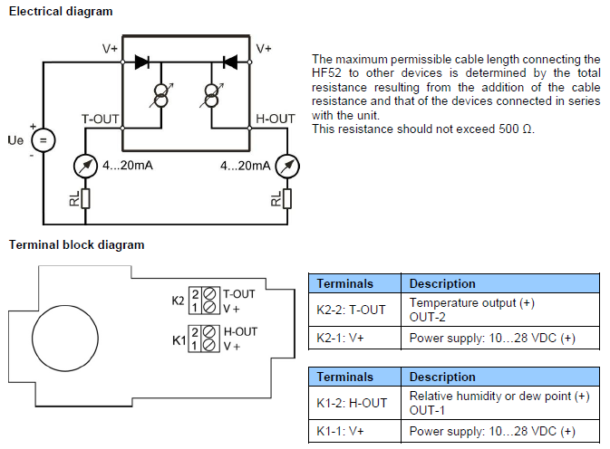
Note: connect the + of the power supply to only one of the V+ terminals. The two terminals marked V+ are internally connected.
Measuring humidity or temperature only: Operation of the HF52 does not require both current loops to be closed. When using the HF52 to measure either humidity only or temperature only, close only the loop that is being used.
Using the ROTRONIC HW5 or HygroSoft software, any unused output of the HF52 can be disabled.
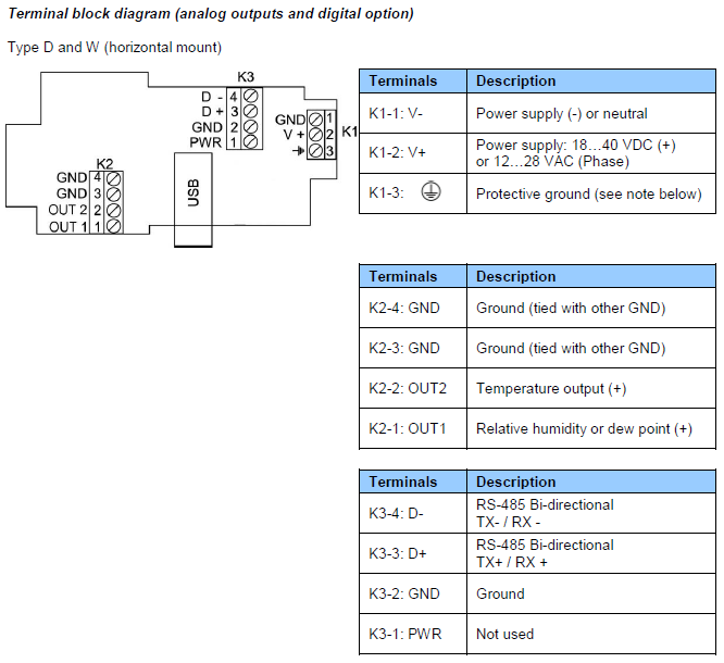
HF53: 3-wire transmitter
Note:
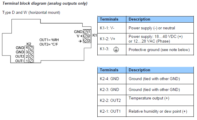
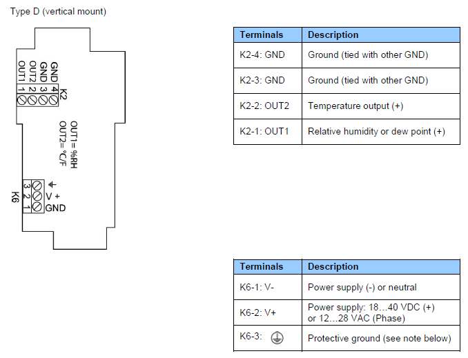
Terminals K1-3 or K6-3 (protective or earth ground) are tied with GND. If this is not wanted, a land (B18) on the PCB must be removed.
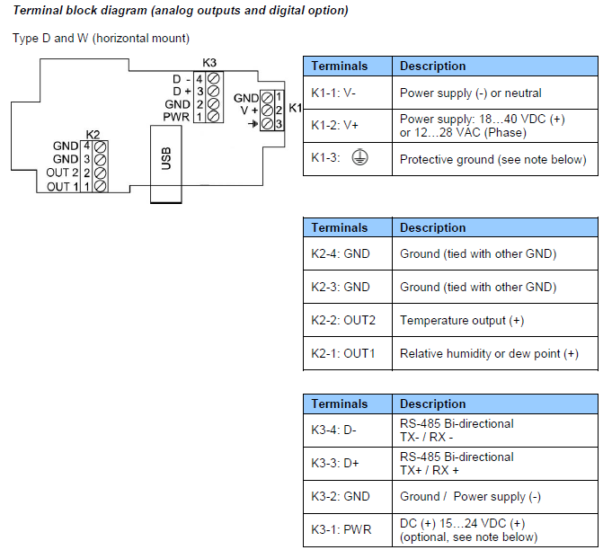
Notes:
Terminal K1-3: this terminal (protective or earth ground) is tied with GND. If this is not wanted, a land (B18) on the PCB must be removed.
Terminal block K3 (RS-485): terminals K3-1 and K3-2 can be used to power the HF53 from a 15 to 24 VDC power supply connected to the RS-485 main data line. In this case, do not use terminals K1-1 and pin K1-2 (normally used to power the HF53).
USB or TCP/IP port: this port is optional
Measuring humidity or temperature only:Operation of the HF53 does not require both current loops to be closed. When using the HF53 to measure either humidity only or temperature only, close only the loop that is being used.
Using the ROTRONIC HW5 or HygroSoft software, any unused output of the HF53 can be disabled.
HF54: 3-wire transmitter, galvanic isolation of the analog outputs
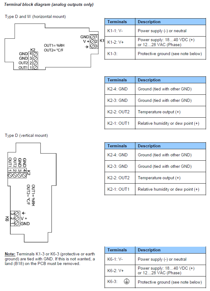
Notes:
Terminal K1-3: this terminal (protective or earth ground) is tied with GND. If this is not wanted, a land (B18) on the PCB must be removed.
USB or TCP/IP port: this port is optional
Measuring humidity or temperature only: Operation of the HF54 does not require both current loops to be closed. When using the HF54 to measure either humidity only or temperature only, close only the loop that is being used.
Using the ROTRONIC HW5 or HygroSoft software, any unused output of the HF54 can be disabled.
HF56: 100…240 VAC supply voltage
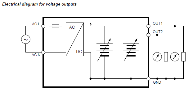
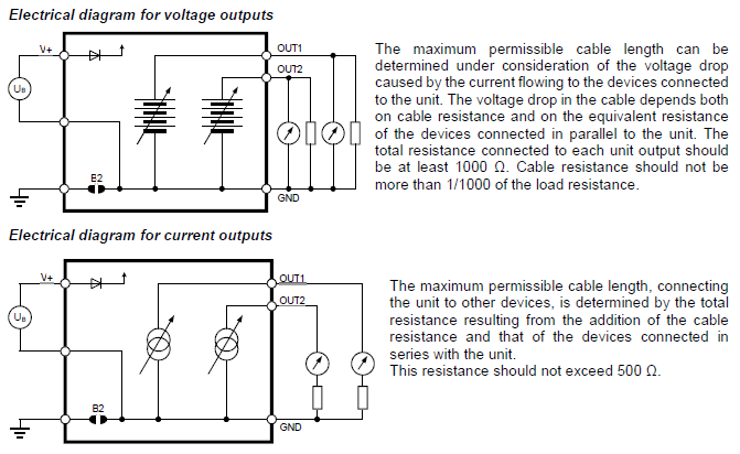
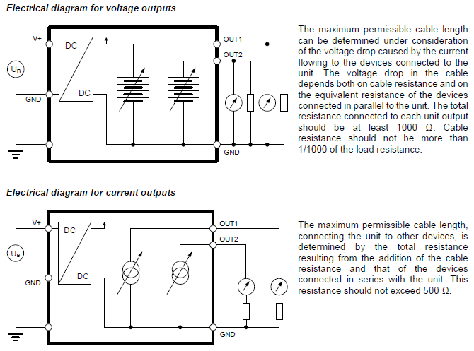
The maximum permissible cable length can be determined under consideration of the voltage drop on the cable.
The voltage drop in the cable depends both on cable resistance and on the equivalent resistance of the devices connected in parallel to the unit.
The total resistance connected to each unit output has to be at least 1000 Ω.
Cable resistance should not be more than 1/1000 of the load resistance.
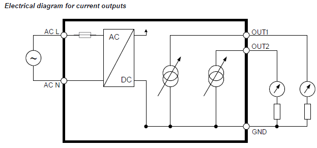
The maximum permissible cable length, connecting the unit to other devices, is determined by the total resistance (cable resistance + devices connected in series with the unit).
This resistance should not exceed 500 Ω.
Measuring humidity or temperature only: Operation of the HF56 does not require both current loops to be closed. When using the HF56 to measure either humidity only or temperature only, close only the loop that is being used.
Using the ROTRONIC HW5 or HygroSoft software, any unused output of the HF56 can be disabled.
Grounding (all models)
We generally recommend grounding the (-) side of the power supply, especially if the electronics will be subjected to a low humidity environment (35 %RH or less)