Overview
This section of the HW5 manual covers only the HW5 functions that are unique to the HF3/4 digital interface. HW5 functions that are not device dependent are covered in General HW5 feature.
Device Manager
The HW5 functions available for the HygroFlex are illustrated below:
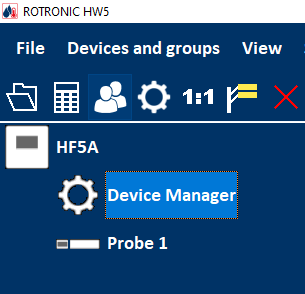
To open the Device manager form, click with the mouse on Device Manager. The Device Manager form is used to configure the HygroFlex and to read device specific information.
When Device Manager is started, it automatically interrogates the device and downloads its current configuration.
Device Information
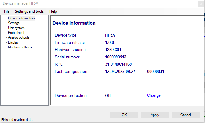
RS485 address: click on the underlined link to change the instrument address to be used in conjunction with an RS-485 network (multi-drop). Each network address should be unique and within the values of 0 to 63.
Note: the default factory RS-485 address is 0. Unless necessary, do not manually modify this address. HW4 will automatically change the RS-485 address of the device, if so required.
Device Protection: for a description of this function, see document General HW5 feature
FORGOT THE PASSWORD? - Power down the device. After powering up the device, you have about one minute to use the default password !resume! (include the exclamation marks). After one minute the default password will be no longer accepted.
Settings
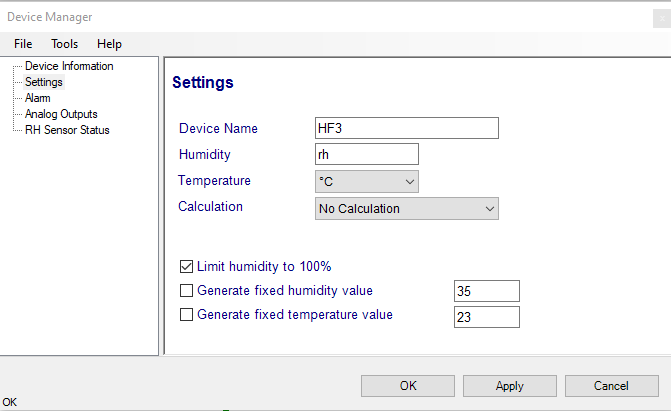
Device name: As far as possible use a unique device name (maximum 12 characters).
Humidity: Possibility to change the abbreviation of the relative humidity, which is different in other languages.
Note: It can only have max. 2 digits
Temperature: Changing the unit of the Temperature from Celsius to Fahrenheit.
Calculation: Adding a third parameter. Dew point (Dp), Frost point (Fp) etc. (depends on the device).
Limit humidity to 100%: typically, the humidity sensor gives a reading slightly above 100 %RH when condensation occurs at the surface of the sensor. Check this box to limit the maximum value of humidity to 100 %RH.
Generate fixed humidity/temperature value: place a check mark in these boxes to make the HygroFlex generate fixed humidity and temperature values instead of the actual measurements.
The fixed values must be with the following limits: -999.99 and 9999.99.
Note: Make sure that the fixed values fall within the range specified for the HygroFlex analog outputs. Using the device as a simulator serves the purpose of verifying the analog signal transmission (loop validation) after completing an installation.
Alarm
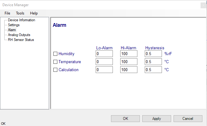
Note: This function has no effect on the device analog outputs and applies only to the transmitter optional display (an alarm symbol appears). The digital communication with a PC via service connector or permanent digital interface will not work anymore with the HW5.
Alarm conditions can be defined for humidity, temperature and the calculated parameter. Values that are below the low alarm value or above the high alarm value will trigger an alarm. The value specified for the alarm function hysteresis is used for both the low and the high alarm.
All versions of HW5 will show an out-of-limits value alarm in red on the monitor screen. In addition, HW5 can be configured (HW5 global settings - Alarm settings tab) to display an alarm table and generate a report whenever an out-of-limits condition occurs.
Analog Outputs
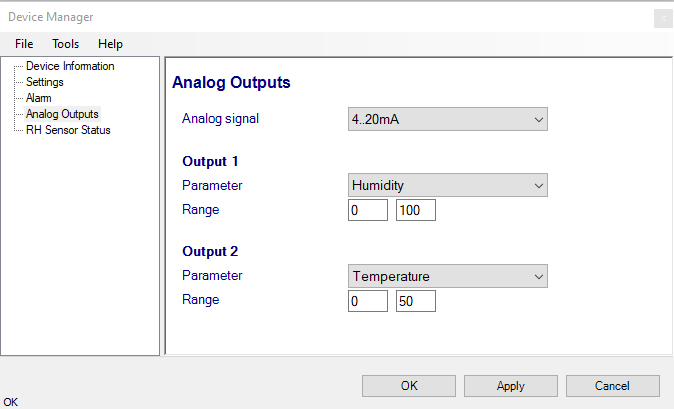
Analog signal: the type of signal for both analog outputs of the 3-wire circuit type can be configured with HW5 as shown below:
0..1V
0..2V
0..5V
0..10V
0..20mA
4..20mA
The analog signal type of the 2-wire, loop powered is always 4…20 mA.
Output 1 and Output 2: select the parameter corresponding to each analog output and the range to be used.
Each output can be made to correspond to the parameters shown on the list. Any output can also be disabled. The output range must be within the numerical limits of -999.99 and 9999.99
RH Sensor Status
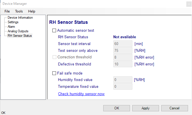
Automatic Sensor Test: place a check mark in this box to enable the automatic RH sensor test.
Sensor Test Interval
Enter the desired time interval for the automatic sensor test (minutes). Recommended value: 60
Test sensor only above
The RH sensor will be tested only when the measured humidity value is equal to or higher than the value entered in this text box.
Default value: 60 (may be changed by factory)
Note: a different test is used to detect major sensor problems such as an open circuit or a short circuit. This test is not affected by the settings entered in this form.
Depending on the test result, the RH sensor status is reported as follows:
Not available
The sensor has not been tested. Verify the RH sensor test settings (Device Manager menu bar > Tools). The sensor will not be tested as long as the current value of %RH is below the value entered in the box labeled “Test above [%RH}”
Good
The sensor error is less than the correction threshold value. The correction offset (SQ) for sensor drift correction is automatically set to zero
SQ-Tuned
The sensor error is equal or larger than the correction threshold value but less than the defective threshold. A correction (SQ) is automatically added to the value measured by the sensor. The correction (SQ) is calculated based on the %RH currently measured by the sensor and on the coefficients A, B and C (RH sensor test settings).
Bad
The sensor error is equal or larger than the defective threshold value
The AirChip 3000 issues a digital alarm only when both of the following conditions are met: (a) the %RH measured prior to the test is at least equal to the value entered in Tools > RH Sensor Test Settings > Test above [%RH] box and (b) the humidity sensor test returns the result “Bad”. When using HW5 to communicate with the HF3/4 transmitter, the text “Bad Sensor Alarm” appears in red on the monitor screen. HW5 Professional can be configured (HW5 global settings - Alarm settings tab) to display an alarm table and generate a report whenever a device alarm condition occurs.
Correction Threshold: place a check mark in this box to enable the automatic RH sensor drift compensation function.
Correction Threshold
Enter the sensor error (%RH) that will trigger a correction. Recommended value: 2 (may be changed by factory)
Defective Threshold
Enter the sensor error (%RH) above which the sensor will be considered to be defective. Recommended value: 5 (may be changed by factory)
Fail Safe Mode: In the event of a sensor failure, this function makes the HF3/4 generate predetermined humidity and temperature values so as to prevent undesirable action by a humidity or temperature control device that relies on the analog or digital signals of the transmitter. Place a check mark in this box to have the HF3/4 generate a fixed humidity or temperature value (both digital and analog) when any of the following occurs:
•RH sensor test returns the result “Bad”
•Major failure of either the humidity or temperature sensor (shorted or open sensor)
The fixed values must be with the numerical limits of -999.99 and 9999.99 and should also be within the range specified for the analog outputs.
Note: The calculated dew or frost point takes a fixed value whenever the value of both temperature and humidity is fixed.
Check Humidity Sensor Now: this link works only when the transmitter is configured with the automatic RH sensor test function enabled and when the measured value of humidity is above the limit entered in the RH Sensor Test Settings form. When both conditions are met, click on this link to manually run a humidity sensor test and eventually have the transmitter a correction to the humidity output signal.
Display (optional)
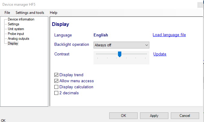
Load Language File: click on this link to change the language of the device internal menu by writing to the transmitter the contents of a language file present on your PC
Backlighting: click on the arrow to the right of the box and select from Always off, Always on or On Key Press
Contrast: use the slider to adjust the contrast of the local LC display and click on the Update link to change the contrast. Click on the Update link to write the new contrast setting to the transmitter.
Enable Trend: check this box to enable the trend indicators on the optional local display. Trend indication in the HW5 Current Values tab is a Global Setting of HW5 (HW5 Main Menu > Settings and Tools > View tab)
Allow Menu Access: this box applies only for models that have a local display and keypad and is used to prevent access to the internal menu of the transmitter.
Display Calculation: check this box to have the display show by default relative humidity, temperature and the calculated parameter.
2 Decimals: check this box to have the display show the values with 2 decimals instead of one decimal