Variants
There are 3 different transmitter variants available, each available with or without display:
Variants |
Description |
Output |
HF5A-21D0300210100 |
2-wire with Display |
Analog 4...20 mA |
HF5A-21X0000210100 |
2-wire without Display |
Analog 4...20 mA |
HF5A-31D0300210100 |
3-/4-wire with Display |
Analog 0(4)...20 mA, 0...5(10) V |
HF5A-31X0000210100 |
3-/4-wire without Display |
Analog 0(4)...20 mA, 0...5(10) V |
HF5A-D1D0300210100 |
3-/4-wire with Display |
Analog 0(4)...20 mA, 0...5(10) V & Digital Modbus RTU |
HF5A-D1X0300210100 |
3-/4-wire without Display |
Analog 0(4)...20 mA, 0...5(10) V & Digital Modbus RTU |
Connection Diagram
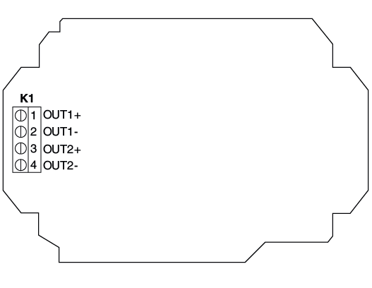
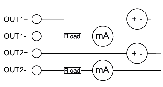
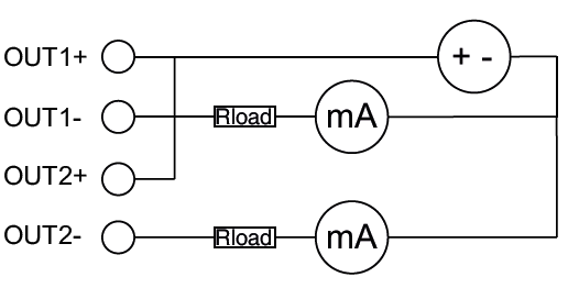
2-wire HF5A-21:
Terminal Overview |
Connection diagram |
|
|
Two separated power supply |
One power supply |
|
|
|
Terminal |
Description |
K1-1-OUT1+ |
Power Supply + |
K1-2-OUT1- |
Analog Output1- |
K1-3-OUT2+ |
Power Supply + |
K1-4-OUT2- |
Analog Output2- |
Note: Recommendation of Rotronic - Two isolated power supply - because the 2 output channels of the HF5A-21 are separated galvanic isolated.
Thus, the device (HF5A-21) and the associated evaluation electronics for each output channel can be accommodated in separate rooms of a building.
3- or 4-wire Setup:
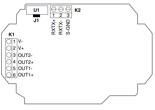
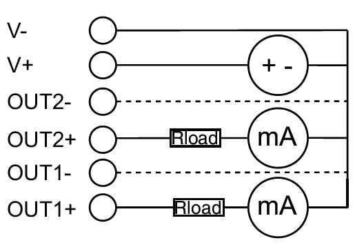
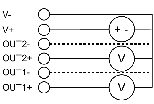
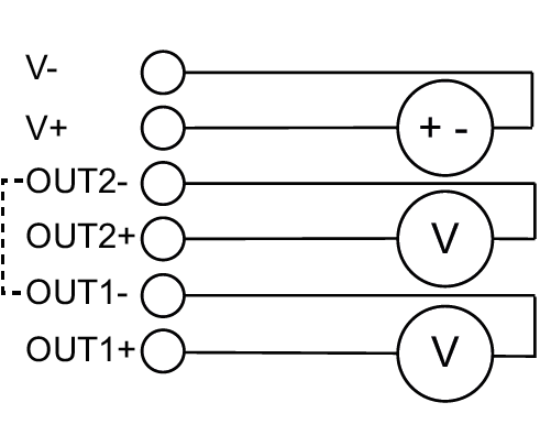
3-wire HF5A-31 & HF5A-D1 / 4-wire HF5A-31 & HF5A-D1:
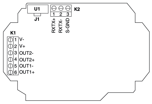
Terminal Overview |
Connection diagram |
|
3-wire (J1 mounted) |
Current |
Voltage |
|
|
|
Terminal |
Description |
K1-1-V- |
Power Supply - |
K1-2-V+ |
Power Supply + |
K1-3-OUT2- |
Analog output 2- |
K1-4-OUT2+ |
Analog output 2+ |
K1-5-OUT1- |
Analog output 1- |
K1-6-OUT1+ |
Analog output 1+ |
Note: Recommendation of Rotronic - 4 - wire galvanic separated with unmounted Jumper J1 - with the benefit that the power supply and the outputs are
separated galvanic isolated. Per default, the Jumper J1 is mounted.
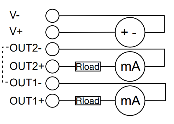
4-wire HF5A-31 & HF5A-D1
Terminal Overview |
Connection diagram |
|
4-wire (J1 unmounted) |
Current |
Voltage |
|
|
|
Terminal |
Description |
K1-1-V- |
Power Supply - |
K1-2-V+ |
Power Supply + |
K1-3-OUT2- |
Analog Output 2- |
K1-4-OUT2+ |
Analog Output 2+ |
K1-5-OUT1- |
Analog Output 1- |
K1-6-OUT1+ |
Analog Output 1+ |
Terminal HF5A-D1 Digital |
Description |
K2-1 RXTX+ |
RS485+ (A) |
K2-2-RXTX- |
RS485- (B) |
K2-3-S-GND |
Signal Ground (-) |
Note: Recommendation of Rotronic - 4 - wire galvanic separated with unmounted Jumper J1 - with the benefit that the power supply and the outputs are
separated galvanic isolated. Per default, the Jumper J1 is mounted.
