RMS-App Configuration
Three stages are required to add a WiFi datalogger to RMS:
1.Configure the RMS-APP (step 1 to step 10). The RMS-APP only needs to be configured once! If you have already configured the RMS-APP, please skip to step 11.
2.Setup the WiFi datalogger (step 11). If you have already setup your WiFi datalogger, please skip to step 12.
3.Configure the WiFi datalogger (step 12 to step 19).
Step |
Description |
|---|---|
Step 1 |
Download the RMS-APP: • Apple: https://apps.apple.com/de/app/rms-app/id6475687150 • Android: https://play.google.com/store/apps/details?id=ch.rotronic.rms.app • Windows: RMS-APP - Monitoring Software | Rotronic | PST
|
Step 2 |
Open the RMS-APP: 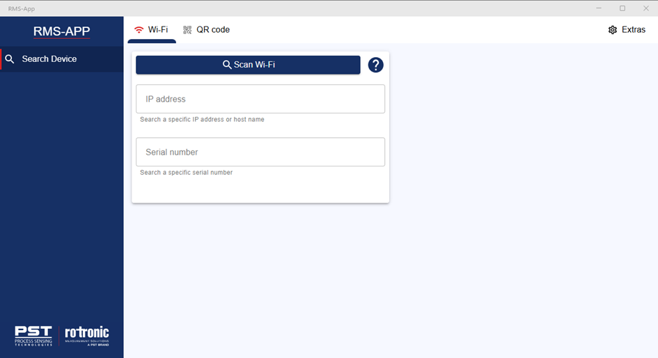 |
Step 3 |
The next step is to add the RMS instance where the WiFi datalogger will be installed.
Click on Extras:  |
Step 4 |
Click on RMS Setup: 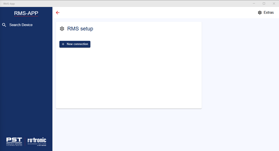 |
Step 5 |
Click on + New connection, click on the drop down: 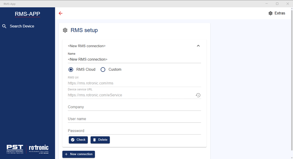 |
Option 1 |
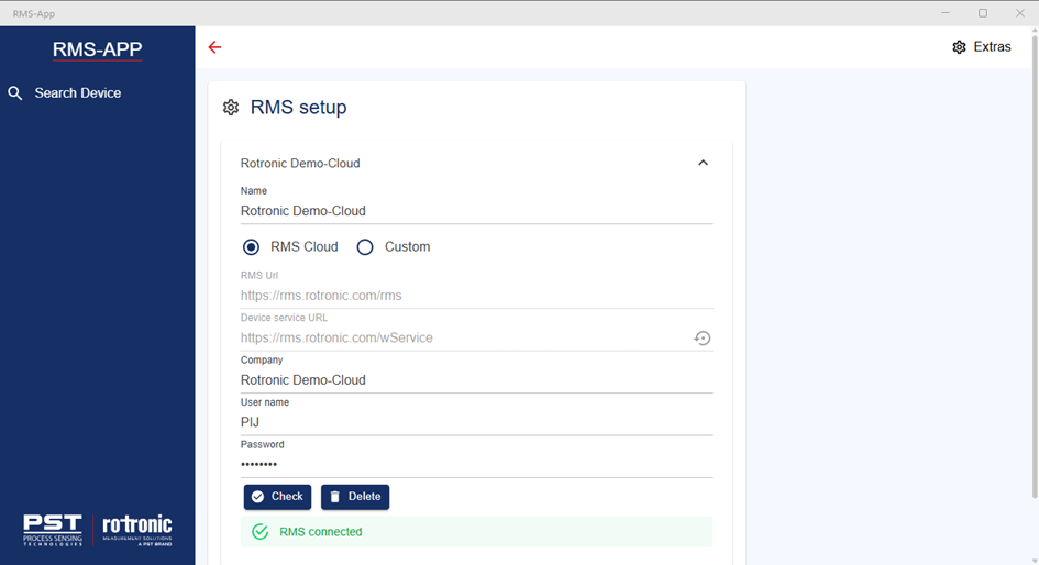
If you are using the RMS Cloud: 1.Add a name for the connection. 2.Select the RMS Cloud 3.Add the RMS company name. 4.Add your User name. 5.Add your Password. 6.Click on Check.
 |
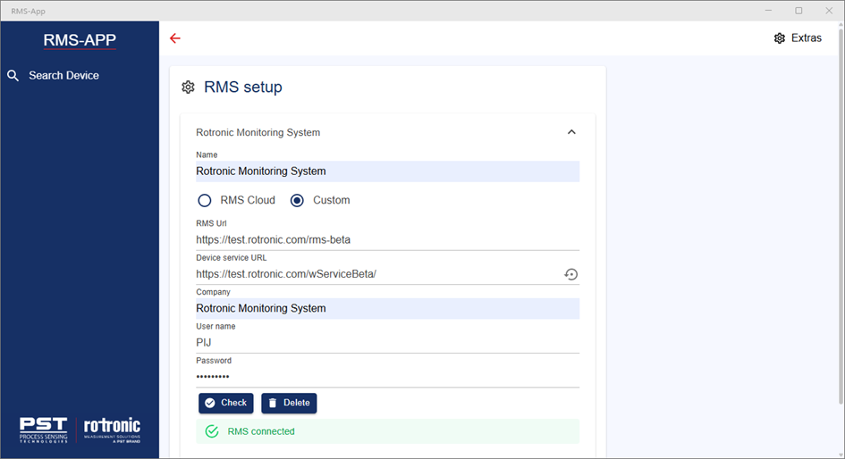
Option 2: |
If you are using the RMS Cloud: 1.Add a name for the connection. 2.Select Custom 3.Add the RMS URL: https://[ServerName]/rms 4.Add the Device service URL: https://[ServerName]/wService 5.Add the RMS company name. 6.Add your User name. 7.Add your Password. 8.Click on Check.
 |
Step 6 |
The next step is to add the WiFi network where the WiFi datalogger will be installed.
Click on Extras: 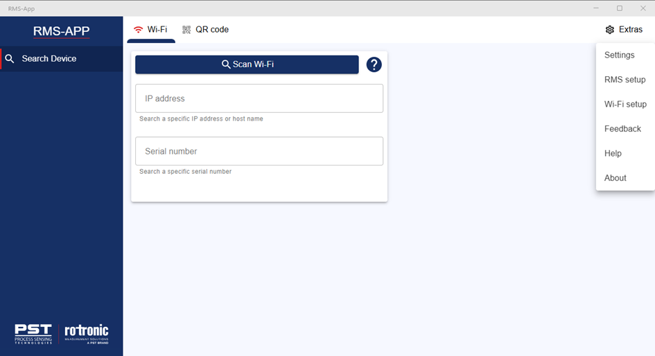 |
Step 7 |
Click on WiFi setup: 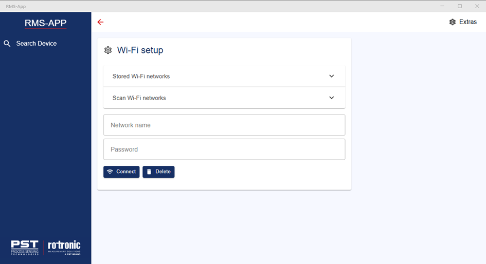 |
Step 8 |
Click on Scan Wi-Fi networks: 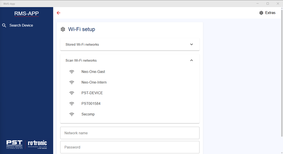 |
Step 9 |
Select the Wi-Fi network from the list, it will appear under the network name, then add the password and click on connect: 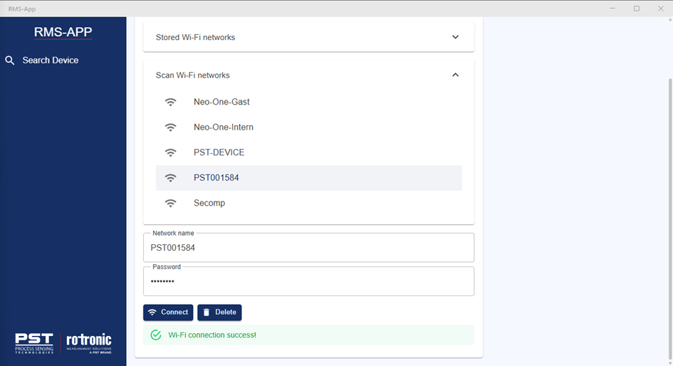 |
Step 10 |
If the network doesn’t appear in the setup, simply manually add the Network name and password and click on connect: 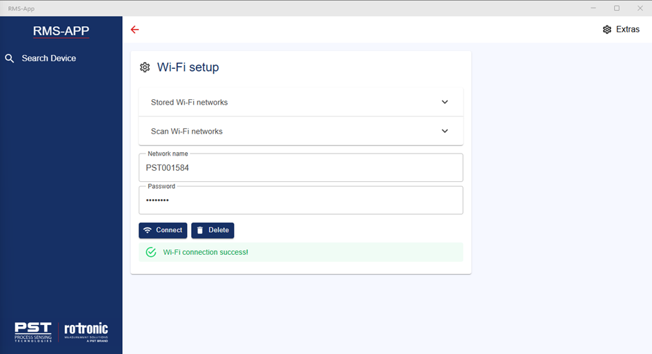 |
Step 11 |
Prepare the WiFi datalogger.
Take the RMS WiFi Logger: •Remove holder. •Remove back plate (Phillips screwdriver required). •Insert 4 batteries (Recommended batteries: Energizer L91 AA Ultimate Lithium 1.5 Volt) . •Recommendation: power the device with a USB C cable. |
Step 12 |
In the RMS-APP, click on search device:  |
Option 1 |
Scan WiFi: 1.Push on the button on the WiFi datalogger for >5s. 2.Click on scan WiFi. 3.The WiFi datalogger will appear in the list: 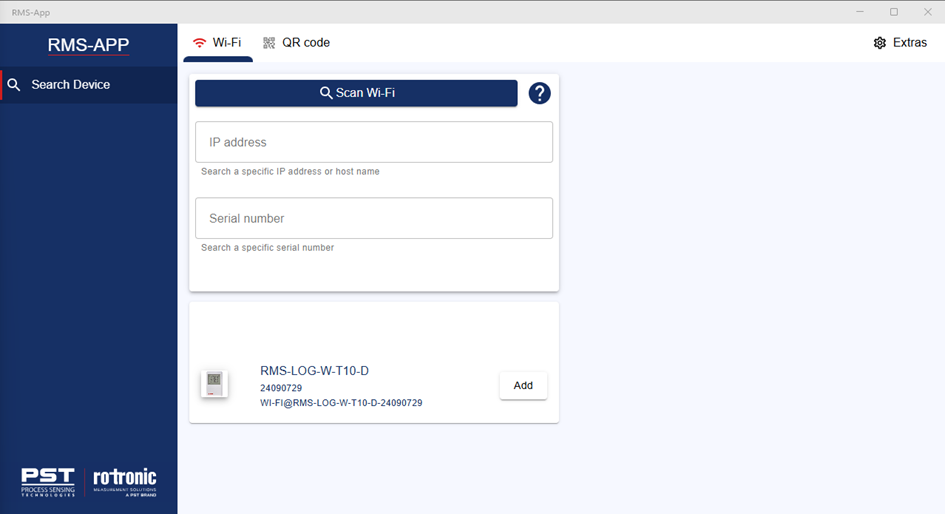
Click on Add, the WiFi datalogger will appear in the list of devices on the left-hand side of the screen and the WiFi datalogger will show added: 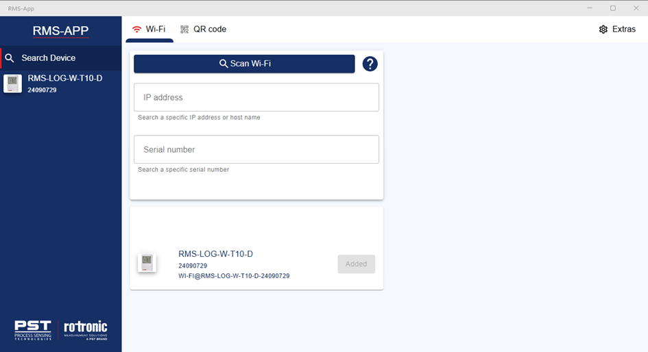 |
Option 2 |
Scan QR code: 1.Click on Scan the QR code. 2.Your camera will turn on. 3.Scan the QR code on the front of the WiFi datalogger. 4.The WiFi datalogger will appear in the list: 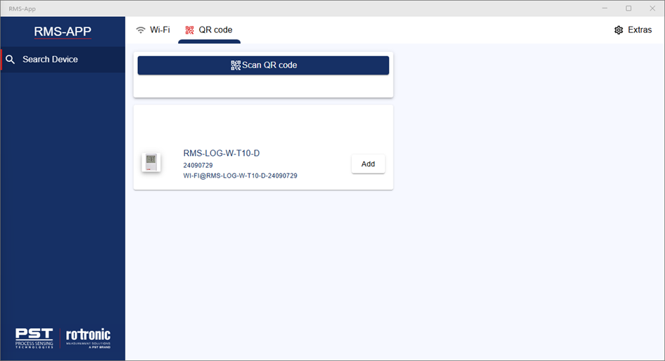
Click on Add, the WiFi datalogger will appear in the list of devices on the left-hand side of the screen and the WiFi datalogger will show added: 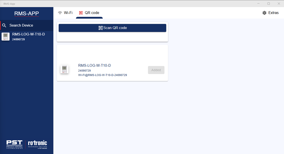 |
Step 13 |
The next step is to configure the WiFi datalogger.
Click on the WiFi datalogger on the left hand side of the screen: 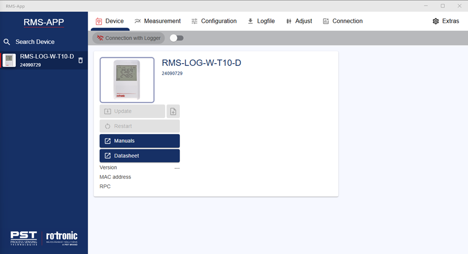 |
Step 14 |
Click on Connection with Logger: 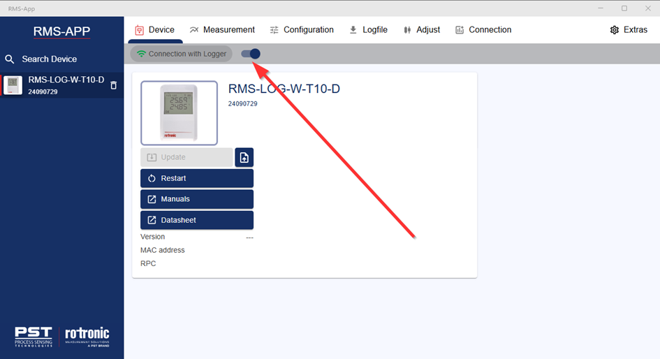 |
Step 15 |
Click on the Connection menu: 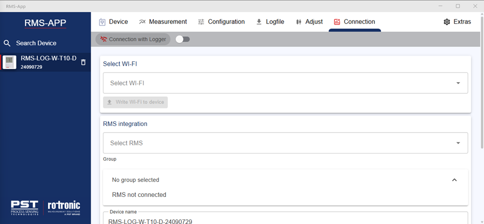 |
Step 16 |
Select Wi-Fi: Click on the Select Wi-Fi drop down and select the pre configured WiFi network: 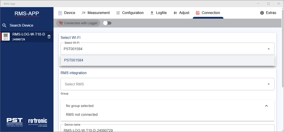
Click on Write Wi-Fi to device to add the WiFi networks settings to the WiFi datalogger. |
Step 17 |
Integrate into RMS: Click on select RMS drop down and select the pre configured RMS company: 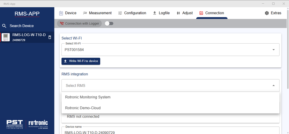 |
Step 18 |
Integration into a specific group: Open the group tree and select the group where the WiFi datalogger should be added: 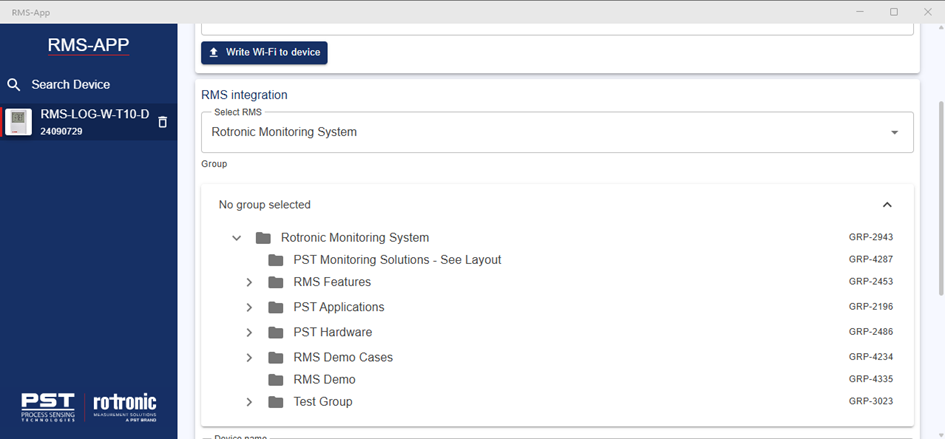 |
Step 19 |
Configure the device name, measurement interval, measuring point name and alarm scheme: 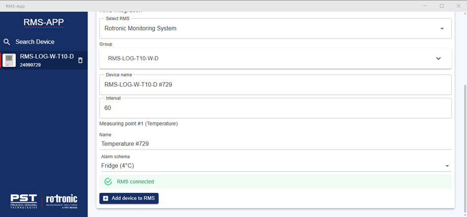
Click on Add device to RMS. |
Step 20 |
Login to RMS to view the WiFi datalogger. |
RMS-App Further function
Topic |
Description |
|
|---|---|---|
Device |
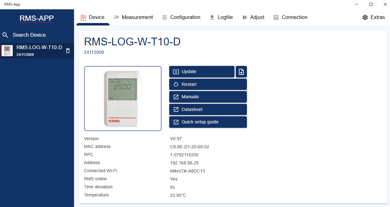
•Firmware update / downgrade •Restart (remote device reset) •Links to device documentation •Live device information |
|
Measurement |
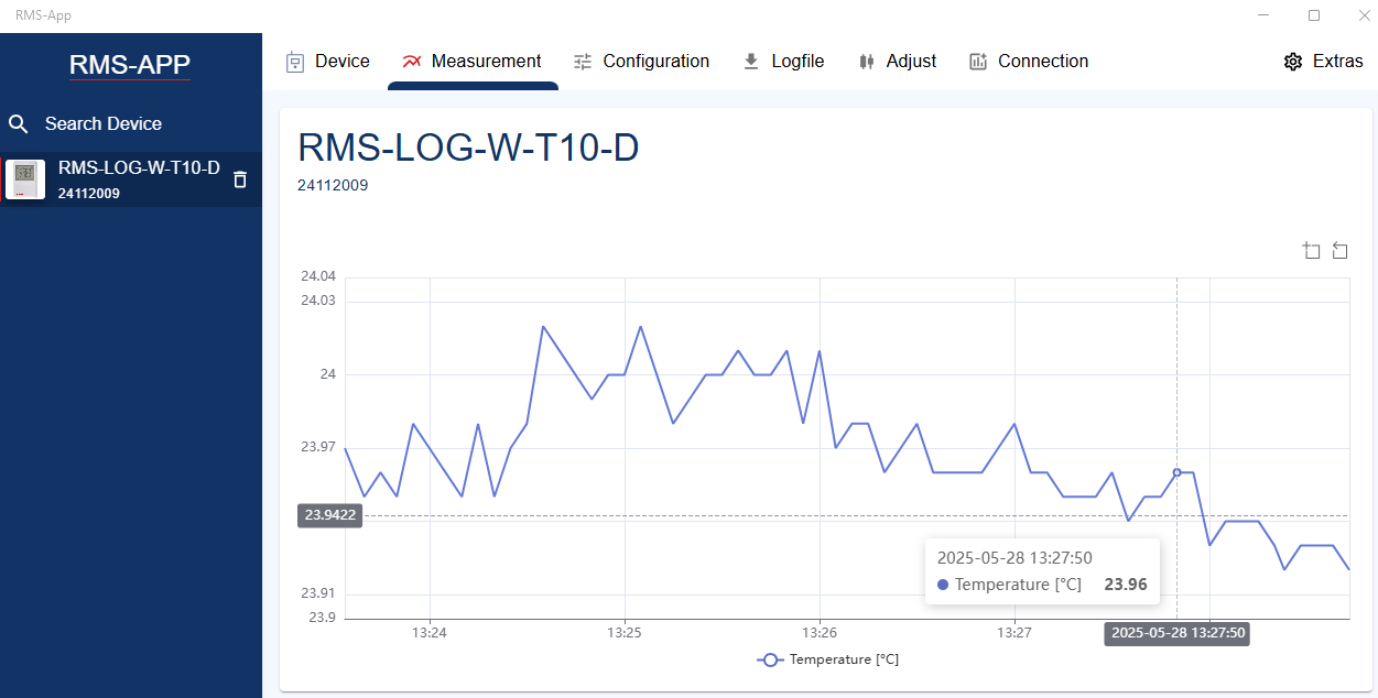
•Measurement value (numeric and chart) |
|
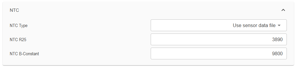
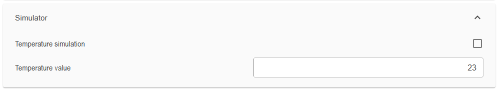
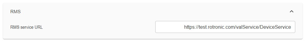
Configuration |
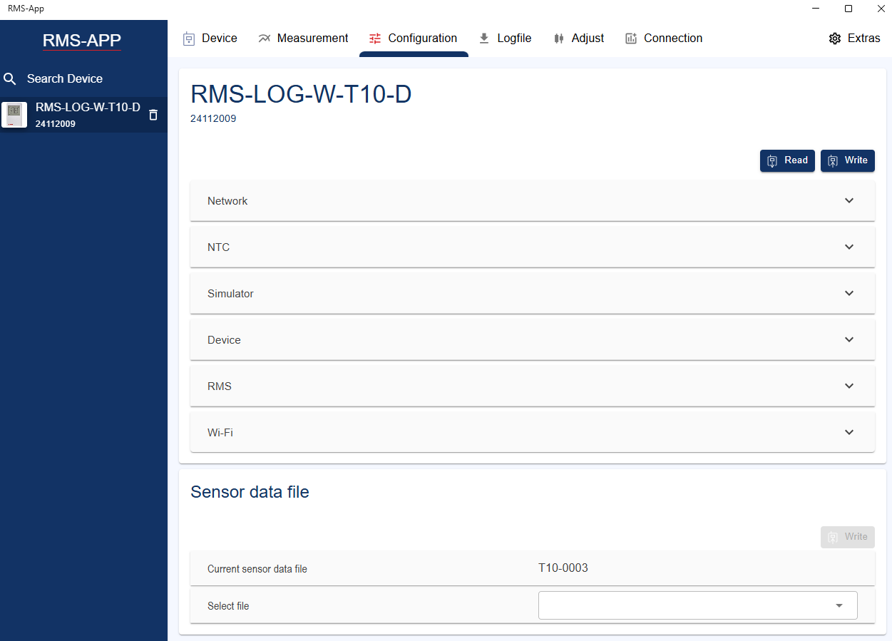
•Please click first the Read button. Then configure and click on the write button. •NTC: The sensor can be configured by Use sensor data file or Use R25 / B NTC parameter. •Simulator: A simulated (not real measured) temperature value can be set and enabled. It is used for system validation. •RMS service URL: Link to the RMS server, to that the logger sends data. •WiFi: Maximum 10 WiFi networks can be stored in the logger. If the current used is not available (interrupt, change of password, change of location etc.), than the logger scans for available networks, compares to this settings and connects to the known WiFi network with the strongest signal strength.
|
|
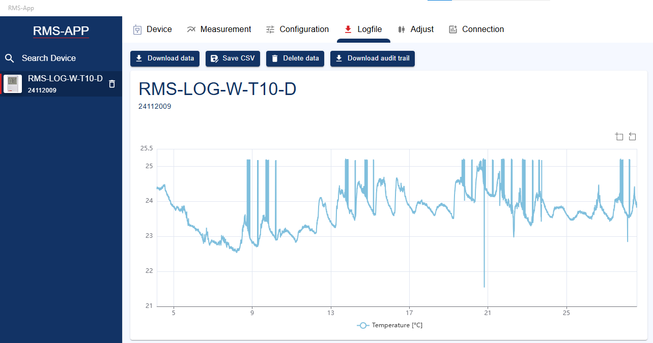
Logfile |
•Download data: current log data (max. 44'000 measurement values) can be downloaded, visualized on a chart or exported into a *.csv file for further analysis manually. The log data can also be deleted. •Download audit trail: The device-internal audit trail contain information about the system health of the device as extraordinary communication. It is very helpful for further system analysis. By clicking the butten Download audit trail, these information can be exported into a *.csv file. |
|
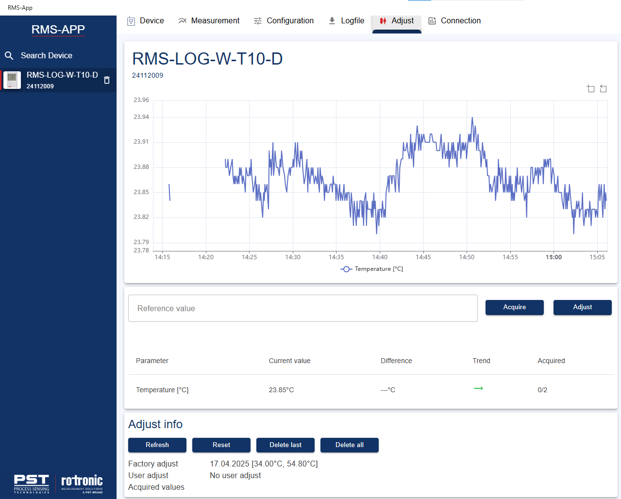
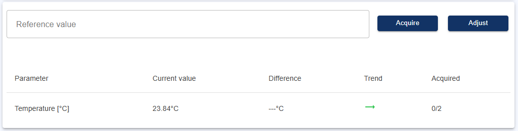
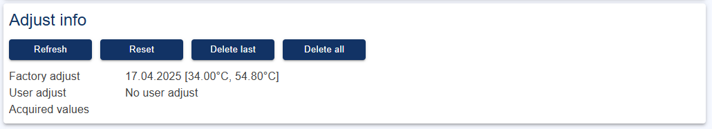
Adjust |
•The measurement chart is very helpful to judge wether the current measurement is stable for adjustment. •In this field, the user can acquire and adjust reference and measured values. (See Adjustment at chapter Device description). Chart and trend indicators can be used to judge whether the climate, UUT and reference are stabilized. •Adjust info contain all current adjustment (production and customer adjustment) information stored in the logger. |
Updated: 16.04.2026