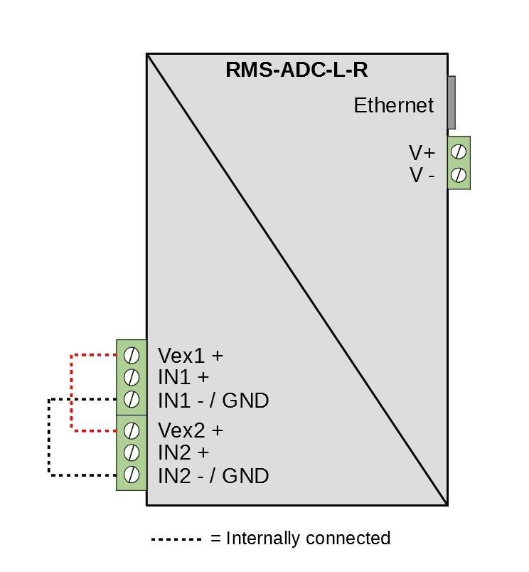
Important: "IN1 -" and "IN 2 -" are internally connected to each other. Depending on the setup, this could cause a ground loop. |
Connection of analog inputs
Marking |
Function |
|---|---|
Vex1+ |
Power supply for sensors (+24 VDC) |
IN1+ |
Analog input + |
IN1- / GND |
Analog input - / GND |
Vex2+ |
Power supply for sensors (+24 VDC) |
IN2+ |
Analog input + |
IN2- / GND |
Analog input - / GND |
Internal connections
"Vex1" and "Vex2" as well as "IN1-" and "IN2-" are internally connected. The device voltage supply (V+/V- or PoE) is galvanic separated from the analog inputs.