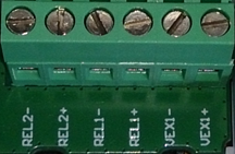
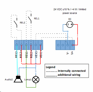
Connection of external power supply
Marking |
Function |
 |
|---|---|---|
V+ |
Power Supply + |
|
V- |
Power Supply - |
Connection of digital inputs
Marking |
Function |
 |
|---|---|---|
VEX1+ |
Power supply for relays (+24 VDC) |
|
VEX1- |
Power supply GND |
|
REL1+ |
Relay 1 + connection |
|
REL1- |
Relay 1 - connection |
|
REL2+ |
Relay 2 + connection |
|
REL2- |
Relay 2 - connection |
Behavior of the outputs
The outputs are only controlled via the web service. If there is a change, it is transmitted to the device at the specified interval. The corresponding relays are switched. When a relay is switched, the LED will flash green (if activated!). If two changes take place at the same time, the LED will flash twice (on either one or both relays).
Behavior in the event of a power failure
If the external power supply fails, the last initial state is restored when the system is restarted until the new state is transmitted by the web service. In the event that the device loses the power supply during an alarm ("switch relay, reset after delay time: (time in seconds)"), the starting position of the relay is set with a restart. This is handled in such a way that the device is otherwise in an undefined state.
VEX power supply
For the supply of, for example, an external relay, the connections VEX+ and VEX- are available. These are taken directly from the supply voltage (V+ / V-) and are not protected against short circuit or polarity reversal.
The maximum current that can be obtained depends on the power supply V+. It should be noted that this shall supply enough current to the output module as well as the connected relays.
When operating the output module via PoE, no external devices can be supplied via the VEX connections.
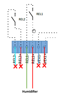
REL2 & REL1 are normally open (NO).


Switch +24V Switch 0V