In case of communication interruption between RMS-CONVERTER-100 and the RMS software, the converter logs the collected data onto the internal memory. As long as the connection is reestablished again, the data will be synchronized between converter and server, this will help avoid any data loss.
MS SQL database
•Data logging
The values of every measurement are saved in the memory with the time stamp.
The RMS-CONVERTER-100 logs data within the on-board MS SQL database: the measurement values and the time stamp. In case of a communication interruption between the RMS server software and the RMS-CONVERTER, the data will be stored for a maximum of 7 days.
Important: •Logging Function •Time difference UTC - local time •Time synchronization |
•Data gaps
In order to avoid data gaps within RMS due to power or communication interrupts:
oThe RMS-CONVERTER-100 and the digital device must be powered via an uninterrupted power supply.
oThe switch must be powered via an uninterrupted power supply.
oThe RMS-CONVERTER-100 and the digital device must be configured with a fixed IP address of the same subnet (only the last numbers of the IP addresses of the devices differ between each other), so that a point to point connection can remain open. The device within the red frame below can communicate with the RMS-CONVERTER-100 should there be a power or communication interruption (higher on the network).
oThe RMS-CONVERTER-100 and the digital device must be on the same switch. If there are multiple digital devices on multiple switches, then Rotronic recommend using an RMS-CONVERTER-100 on each switch.
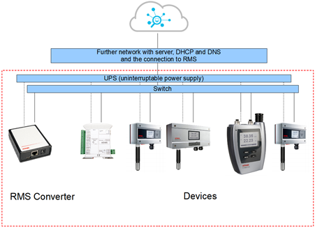
Figure 1: Recommendations for setting up the RMS-CONVERTER-100 on a network.