The safety of the installed system, where the device is integrated, is the responsibility of the builder of the system.
General guidelines
Power supply wiring
Heavy machinery and instrumentation should not share the same power supply wiring. If this cannot be avoided, noise filters and surge protectors should be used. Most UPS devices have those features already integrated.
General guidelines for signal cables
The following guidelines are derived from European Standard EN 50170 for the transmission of signals by copper wires. When planning an installation, the rules provided by EN 50170 should be followed under consideration of local circumstances to determine the position of machines and equipment.
All ROTRONIC products are tested for Electromagnetic Compatibility according to EMC Directive 2004/106/EG and following European standards:
- EN 61000-6-1, EN 61000-6-2
- EN 61000-6-3, EN 61000-6-4
Whenever the level of electromagnetic interference is expected to be high, both the instruments and signal cables should be placed as far away as possible from the source of interference.
In general, signal cables should be installed in bundles or channels / conduits, separate from other cables as indicated in the table below:
•Bus signals such as RS485 •Data signals for PCs, printers etc. •shielded analog inputs •unshielded direct current (<= 60V) •shielded process signals (<= 25 V) •unshielded alternate current (<= 25V) •coaxial cables for CRT monitors |
in common bundles or channels / conduits |
•direct current from 60 V to 400 V (unshielded) •alternate current from 25V to 400 V (unshielded) |
in separated bundles or channels / conduits, without minimum distance / |
•direct and alternate current > 400 V •(unshielded) •Telephone lines •lines leading into EX-rated areas |
in separated bundles or channels / conduits, without minimum distance |
Lightning protection
Cabling in areas with a risk of lightning requires a lightning protection. For cabling underground in between buildings, we recommend the use of special fiber optic cables. If this is not possible, use copper cables that are suitable for underground installation.
Cable grip and cable specifications
All types have one M12 sealing cable grip. This cable grip provides effective sealing only with cables having the proper outside diameter.
Wiring
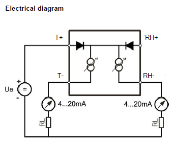
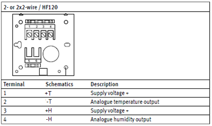
HF120: 2-wire, loop powered transmitter
Terminal block diagram for type W, D and F
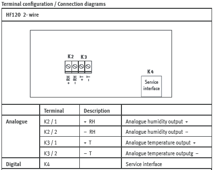
Terminal block diagram for type S
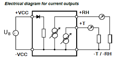
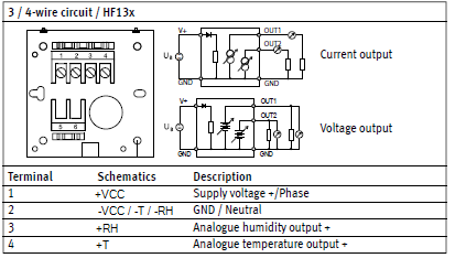
HF13x: 3-wire transmitter
Terminal block diagram for type W, D and F
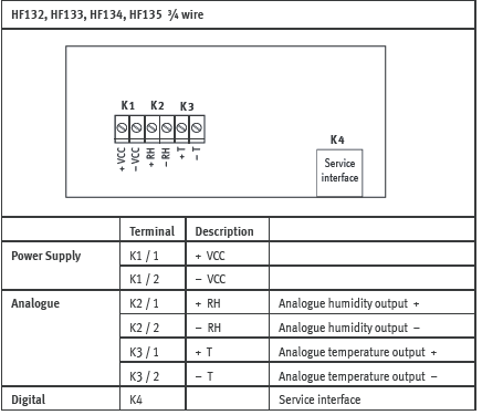
Terminal block diagram for type S
Grounding (HF120, HF13x)
We generally recommend grounding the (-) side of the power supply, especially if the electronics will be subjected to a low humidity environment (35 %RH or less).