General guidelines
Relative humidity is extremely dependent on temperature. Proper measurement of relative humidity requires that the probe and its sensors be at exactly the temperature of the environment to be measured. Because of this, the location where you choose to install the probe can have a significant effect on the performance of the instrument. The following guidelines should guarantee good instrument performance:
Select a representative location: install the probe where humidity, temperature and pressure conditions are representative of the environment to be measured.
Provide good air movement at the probe: air velocity of at least 200 ft/ minute (1 meter/second) facilitates adaptation of the probe to changing temperature.
Avoid the following: (1) Close proximity of the probe to a heating element, a cooling coil, a cold or hot wall, direct exposure to sun rays, etc. (2) Close proximity of the probe to a steam injector, humidifier, direct exposure to precipitation, etc. (3) Unstable pressure conditions resulting from excessive air turbulence.
Immerse as much of the probe as possible in the environment to be measured.
Prevent the accumulation of condensation water at the level of the sensor leads: Install the probe so that the probe tip is looking downward. If this is not possible, install the probe horizontally.
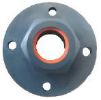
Type D – through wall mount
Part AC5005 is a flange with compression fitting that is designed to hold the probe of the HF3 type D when mounted through a wall. The HF3 does not require any additional support. The AC5005 allows easy installation and removal of the HF3.
Type W – surface mount
The transmitter housing can be attached to the mounting wall using screws with an approximate diameter of 3 mm (1/8”).
Type R and S – surface mount
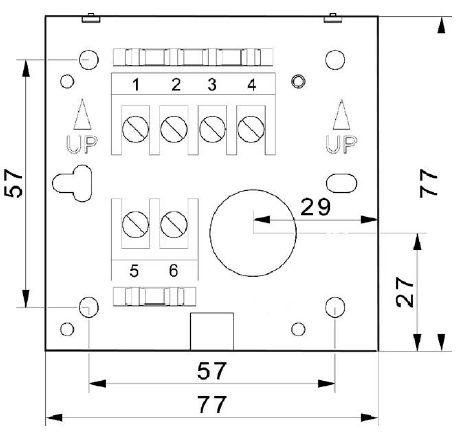
Type R and type S consist of a base plate and an electronics module that plugs into the base plate. The base plate is installed and wired first.
The base plate should be installed with terminals 1 to 4 placed on top. Preferably, use a cable with 18 AWG wires.
Once the base plate has been installed and wired, the electronics module can be inserted and secured with the screw provided.
Note: dimensions in mm
Type S – Ventilation

Insufficient ventilation on the Sensor can result in an additional temperature measurement error of +1,5 °C (self-heating effect).