PC62V
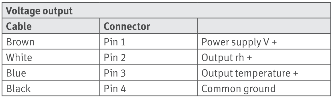
Connect the supplied cable connector to the sensor. Use the following table to make cable connections to the appropriate hardware.
NEW connections
PC62
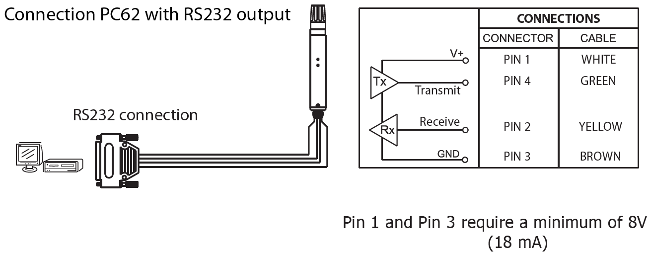
The PC62 communicates with any computer or PLC equipped with an RS232 interface.
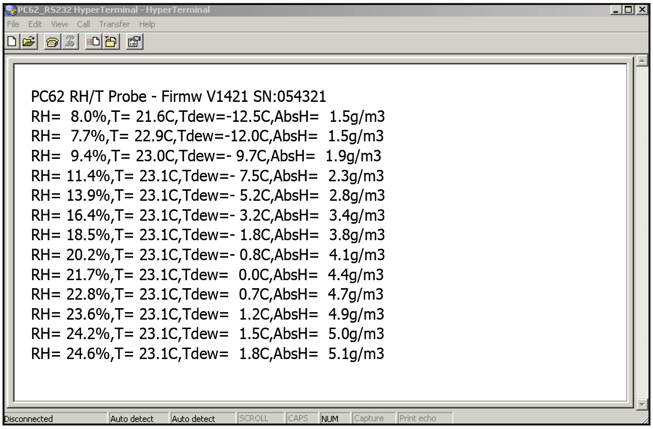
Below is a HyperTerminal screenshot showing the output right after supplying power to the probe:
The first line shows specific information about the probe.
RH=46.4%, T=23.1°C, Tdew=11.0°C, AbsH=9.6g/m3
A terminal program is an application that will enable a PC to communicate directly with a modem, for example, an RH transmitter. This can be useful to test the modem’s availability and diagnose problems. If Windows 2000 or Windows XP is being used, the Windows HyperTerminal program is included as part of the operating system.
When the PC62 is correctly connected with the PC and a terminal program is used, the RH information is visible on the screen.
In the terminal program use the next parameters for communication:
Baud-rate 9600
Data bits 8
Parity none
Stop bit 1
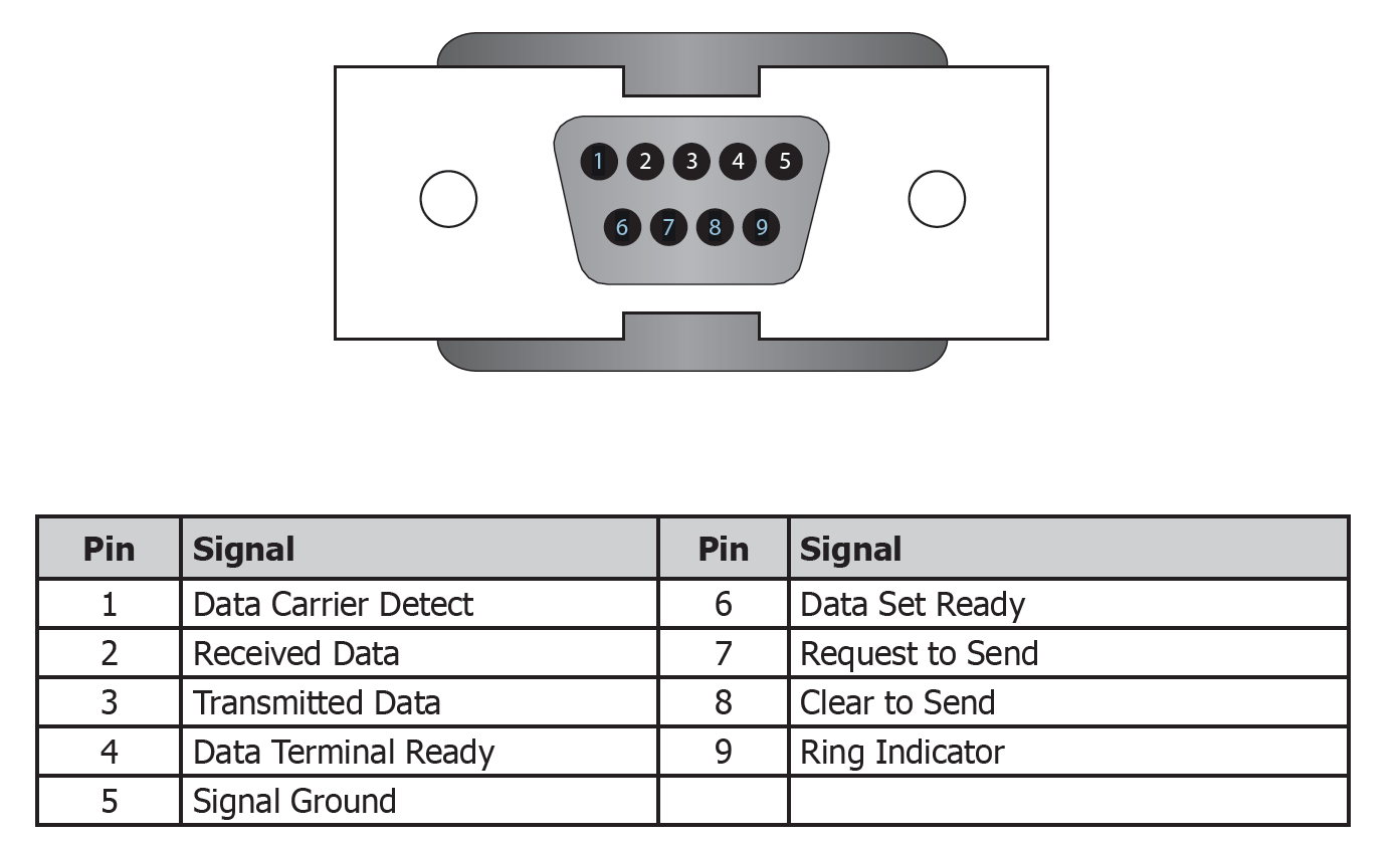
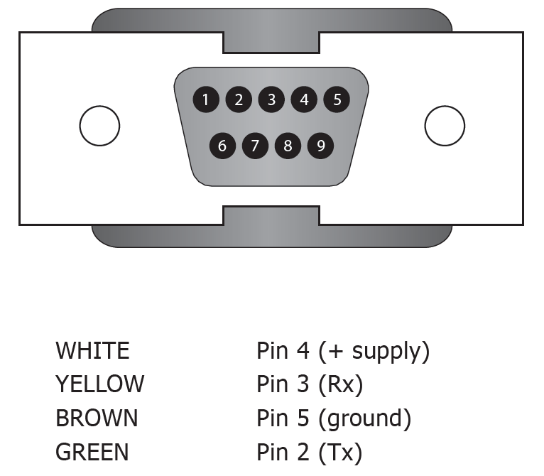
Connecting the 9-pin RS232 Sub-D connector
In order to connect the PC62 to a PC with a 9-pin serial interface, a 9-pin female Sub-D connector is needed.
6 7 8 9
 1
1
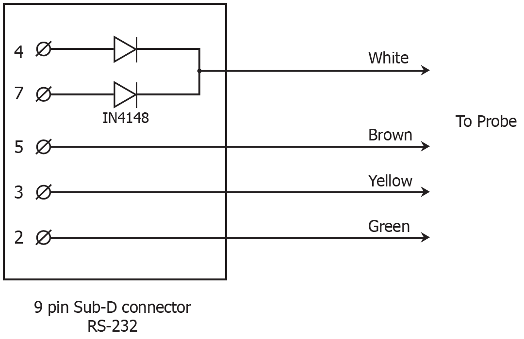
The wires of the PC62 cable should be connected as follows:
NOTE: The 8V to power the instrument could be supplied by the RS232 port of a PC. (See schematic below). RS232 is getting more scarce and USB is seen more often. In this case a USB to RS232 converter could be used utilizing the same connections. However, most converters lack enough power and an external power supply would be necessary if this was the case.
PC62 WITH RS485 OUTPUT
When the PC62 is ordered with an RS485 it becomes an addressable transmitter enabling a maximum of 32 units to be connected to a single two-wire bus. The transmitter acts as a slave and will only provide data output when requested by the system.
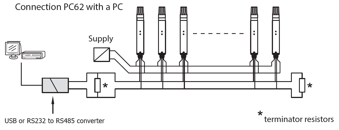
*only at the beginning and end of the data cable, value depends on cable Impedance
WHITE Pin 1 (+ supply)
YELLOW Pin 2 (B)
BROWN Pin 3 (ground)
GREEN Pin 4 (A)
•The address (0 to 255) is stored in ASCII format in the memory of the transmitter. It is possible to change the address and adjust the calibration parameters.
•The information on the command set is available by contacting your local Rotronic partner.
•The RS485 transmitters are, by default, set to address ‘01’.
•Below is an example string of ASCII coded data:: Addr:01,RH= 26.8%,T= 22.6C,Tdew= 2.6C,AbsH= 5.3g/m3
The PC62 starts up in normal operation mode. The instrument must be in this mode before requesting data from the PC62 with a RS485 output. The COM port parameters are:
9600 Baud rate; 8 data bits; No Parity; 1 Stop bit
Command string format: 0x02 0x1D 0x?? 0x?? 0x03
(STX cmnd Addr Byte 1 Addr Byte 2 ETX)
Addr Byte 1 and 2 form the ASCII coded address of the sensor.
Example:
The probe should respond to a query command sent to address “10”.
ASCII code for “10” is 0x31 and 0x30.
Sending the following string will give a response of the probe with address “10”.
0x02 0x1D 0x31 0x30 0x03
Below is an example string:
Addr:10,RH= 19.3%,T= 23.0C,Tdew=- 1.3C,AbsH= 4.0g/m3