•Calibration certifications: In addition to the normal calibration procedure, each transmitter can be supplied with its own traceable calibration certificate. Please ask Rotronic or your local distributor for more information.
•Calibration interval time: Under normal ambient conditions (0 to 50°C, 20 to 70% RH) and for accuracy of ±2% RH, an annual calibration is recommended. For accuracy of ±5% RH a calibration is recommended every five years. For environments with airborne chemicals or of high humidity and high temperature conditions more frequent calibration is recommended.
If a humidity generator is being used, an adjustment tube should be used to protect the PCB and sensor. For more information on these adjustment tubes please contact Rotronic or your local distributor. A humidity generator, used in combination with a general reference handheld hygrometer, is ideal for a quick and accurate calibration. For more information on the S503, S904 or Optical humidity generators please contact Rotronic.
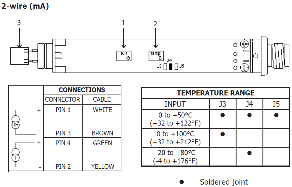
Calibration & Adjustment for 3% Accuracy (1pt Adjustment)
PC33
1.Remove the screw at the side of the connector.
2.Carefully unscrew the sensor protection cap from the head.
3.Carefully remove the circuit board from the body by pulling on the threaded end while holding the tube.
▪ The transmitter should be calibrated at one point, for example 50% RH.
▪ Once this value is reached and the reading of the reference has stabilized, adjust the transmitter with the RH potentiometer (see 1 below).
▪ For versions with a T output the temperature should be calibrated at ambient temperature.
▪ After stabilizing, adjust with the temperature potentiometer (see 2 below).
See picture for 2-wire V DC power supply voltage, output 4-20 mA and Figure 6 for 3/4-wire V DC power supply voltage, output 0 to 1, 0 to 5 or 0 to 10 V.
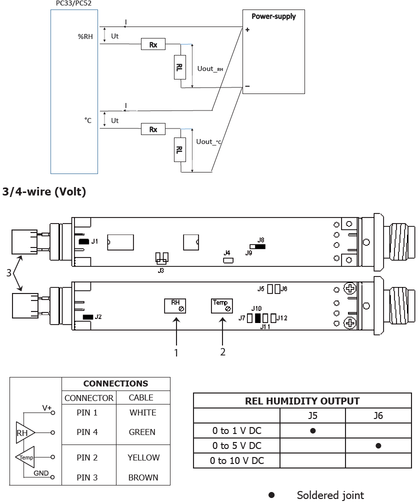
Supply voltage
The specified supply voltage of this transmitter is 4,5..35 Vdc. To prevent a self heating effect which will influence the measurement, it is necessary to keep the voltage across the transmitter as low as possible. We advise a supply voltage of approx. 10 volt across the transmitter at 20 mA current. If not possible, place a resistor in series with the supply, so that the voltage across the transmitter will be 10 Volt at 20 mA.
Example:
See drawing: Ut is the supply voltage. Rx is the load resistance
UI is the voltage across the transmitter and I is the current.
Up = 24V and RL = 50Ω and I = 20mA
Rx= (Up - U1)/I - RL => Rx = (24V - 10V) / 0.02 - 50Ω =>
Rx = 14 /0.02 - 50=> Rx + 650Ω
A good choice is a resistance from 620 Ω.
(Do not place this resistor in the transmitter housing)
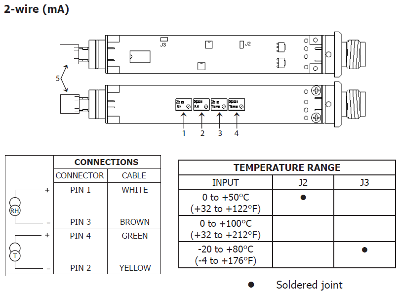
Calibration & Adjustment for 2% Accuracy (2 pt Adjustment)
PC52
1.Remove the screw at the side of the connector.
2.Carefully unscrew the sensor protection cap from the head.
3.Carefully remove the circuit board from the body by pulling on the threaded end while holding the tube. The transmitter should be calibrated at two points, one low (Zero) and one high (Span) point.
• Once the first low value is reached and the reading of the reference is stabilized, adjust the transmitter with the Zero RH potentiometer (see 1 below). Compare with the reference.
• After the second high value is reached and stabilized, adjust with the Span RH potentiometer (see 2 below).
• For versions with a T output this procedure should be repeated with a temperature potentiometer (see 3 and 4 below) only use the “Zero temp” potentiometer to adjust the temperature readings.
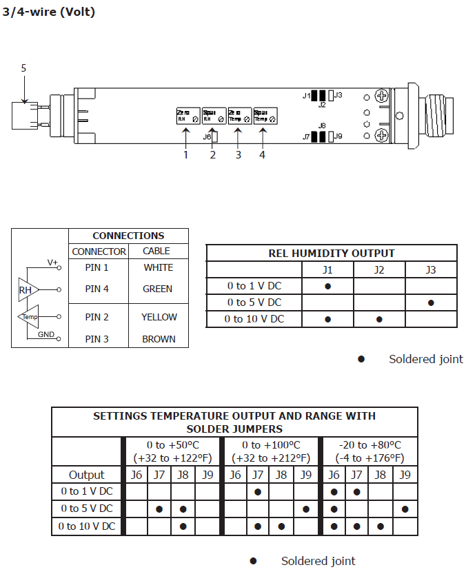
See Picture for 2-wire V DC power supply, output 4-20 mA and Figure 8 for 3/4-wire V DC power supply voltage, output 0 to 1, 0 to 5 or 0 to 10 V.