Web Server Structure
Step 1 |
To access the server, run the Web browser and edit the IP address of the device in the address Bar .
The following window will appear:
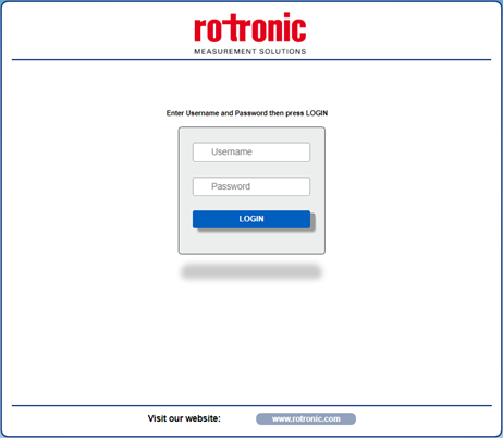
NOTE: oDepending on the Web browser used, some icons and/or writing may vary in shape and color. oIf necessary, it is possible to connect to Rotronic website to download the device's data sheet and user guide. For this, clicking on the "www.rotronic.com" button at the bottom of the window.
|
Step 2 |
Enter the Username and Password. If the default settings are in use, the parameters to access the site are: oUsername: Fact_user oPassword: Fact_pwd
Click on the "Login" button to access the device's home page. It will appear as follows:

NOTE: For all web pages going forward, you will find the following options: oBack: Return to the page previously visualized oHome: Return to the main page oLogout: Leave the session and return to the Login page
|
Step 3 |
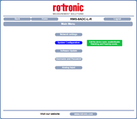
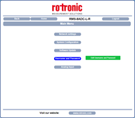
To access the main menu page of the device, select a language and click "OK".
The following window will appear:
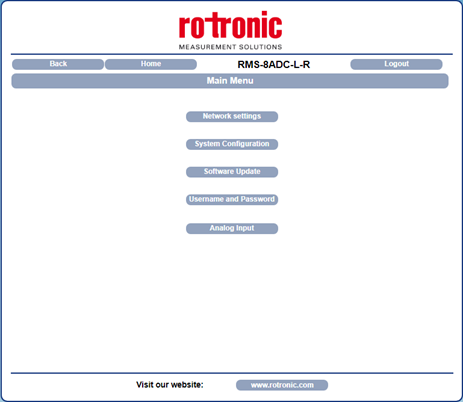
From this page, it is possible to access the internal configuration parameters of the device (as described in the table below).
|
Internal configuration parameters of the device
Segment |
Purpose |
Sub-segments |
Detailed description |
|---|---|---|---|
Network Settings
 |
Set the Ethernet communication parameters |
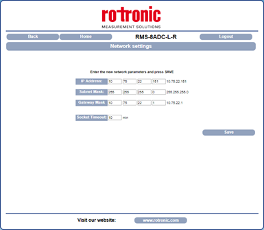 |
oIP Address: View and modify the device's unique IP address. oSubnet Mask: Set the parameter of the Subnet Mask in order to determine the device's local network. oGateway Mask: Set the parameter of Gateway Mask for the correct addressing of the device. oSocket Timeout: Set the timer (in minutes). When the timer expires (unless it is provided with further commands), the device will close the communication socket.
NOTE: When modifying these parameters, save and wait for the device to reset for the new parameters to apply. |
System Configuration
 |
Set the system configuration parameters |
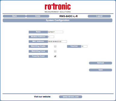 |
oName: Name of the device. oModbus Address: Modbus address of the device. This parameter is forced to 245 in INIT condition. oMAC Address: MAC address of the device oWatchdog Enable, Timeout, Watchdog Event: Watchdog function is not supported by RMS. oPower-up Event: This parameter is set at 1 at each power on. 1 indicates that the device has been switched off or a reset has occurred. If this is set at 0, the device did not power off.
NOTE: Once saved, to read the new parameters on the device, click the Refresh button. |
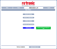
System Update
 |
Access software upgrades if available
|
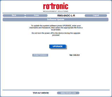 |
This section allows access to the firmware and web server upgrades.
To execute the update, click on the "Upgrade" button. The system will open a pop-up window where the required credentials will need to be inserted in order to proceed.
The parameter "Actual Firmware" shows the current firmware version loaded on the device. |
User name and Password
 |
Set new login details |
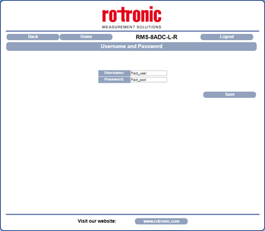 |
This segment is used to set a user name and password. oUsername: Set and visualize the user name for the device. Default: Fact_user oPassword: Set and visualize the password for the device. Default: Fact_pwd
NOTE: Once saved, the changes apply immediately. |
Analog Input
 |
oVisualize the value of the analog inputs oProvides the option to disable certain inputs |
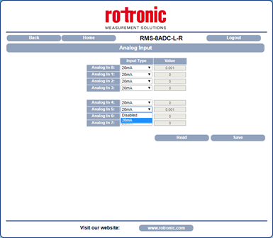 |
In this segment, the user can view the value of the analog inputs expressed in mA.
oInput Type: Provides the option to enable or disable the current input. Each input can be disabled if required. oValue: Shows the value contained in the register associated to the analog input. The "Read" button updates the value read from the device.
NOTE: To save the modifications relating to the Input Type, click the "Save" button. |
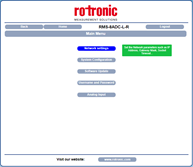
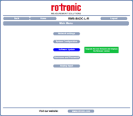
Note: Hovering the cursor over the sections of the initial menu will provide you with a description of each segment. |