Wall Mount Modules include:
1.RMS-GW-868/915.
2.RMS-LOG-L/868/915.
3.RMS-LOG-T30-L/868/915.
4.RMS-D-L.
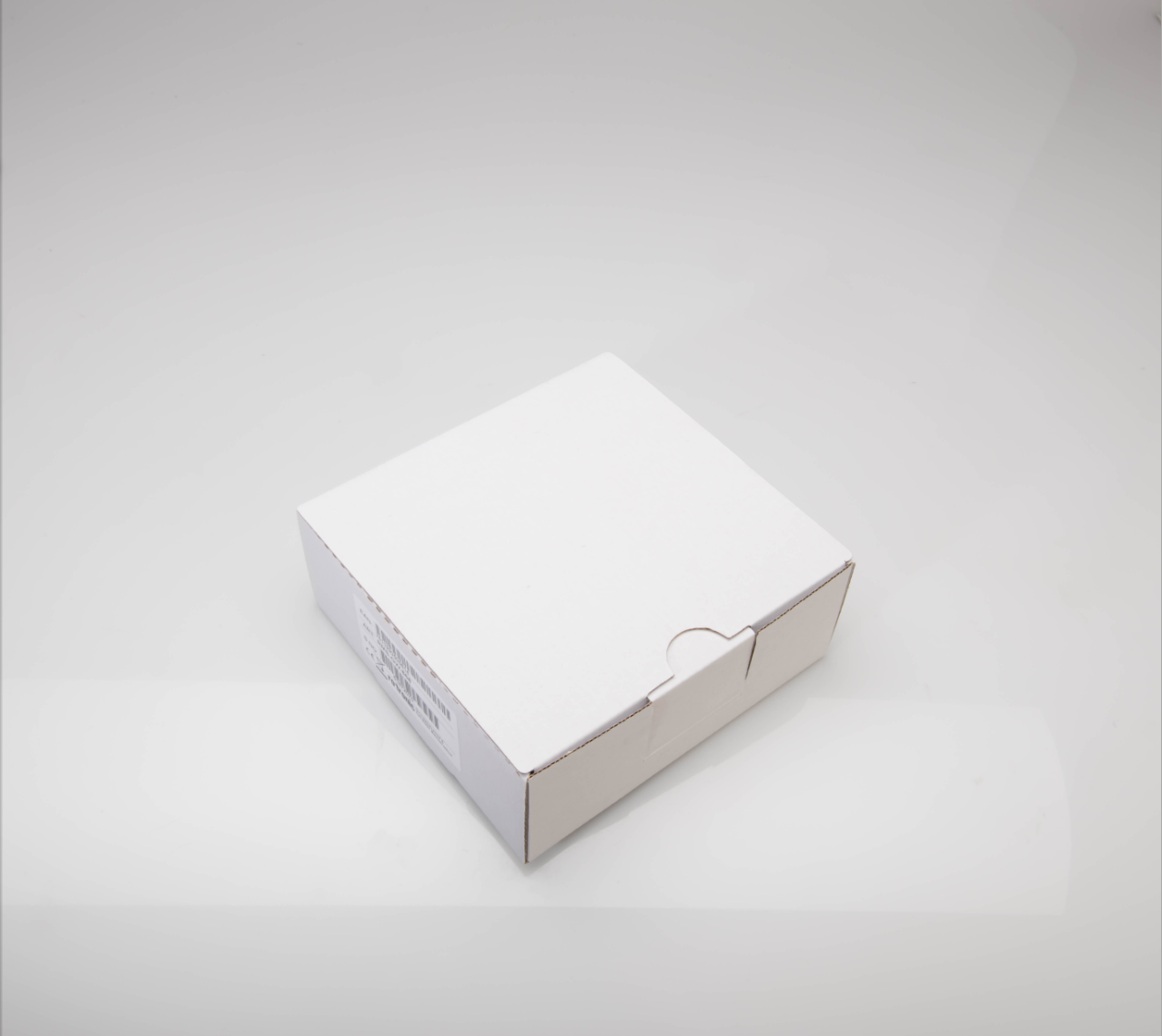
Step 1 |
|
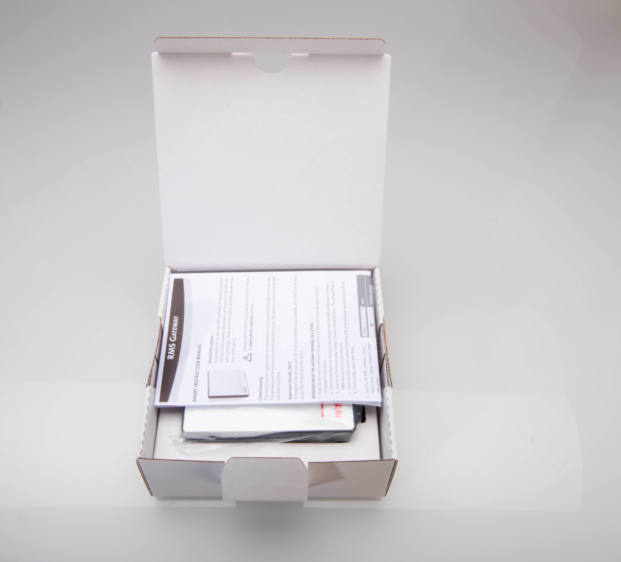
Step 2 |
|
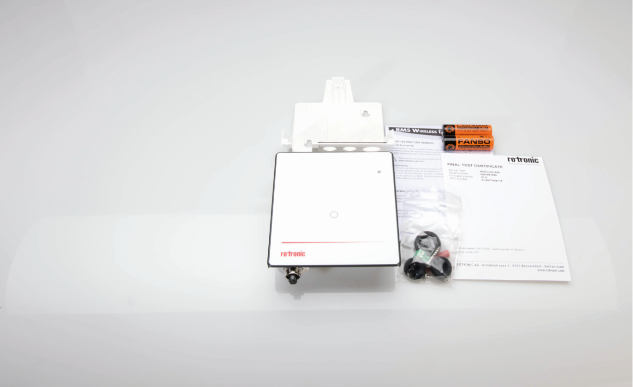
Step 3 |
Package contents: 1 * Wall mount module, including back plate. 1 * Short User Manual. 1 * Final Test Certificate. 1 * Mounting kit (2 screws and wall fixings, joints, power connector to use with the RMS-PS, jeweler screwdriver, velcro). When ordering an RMS-LOG-T30-L/868/915 additional connectors for the Pt100's as well as cable glands are also included. 2 * RMS-BAT batteries (not included with the RMS-GW or the RMS-D-L). 1 * Name / Calibration Date Stickers. |
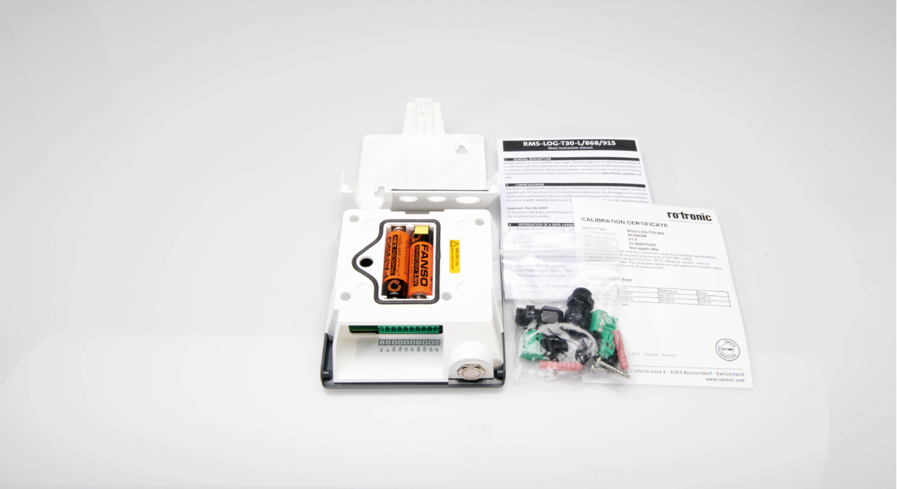
Step 4 |
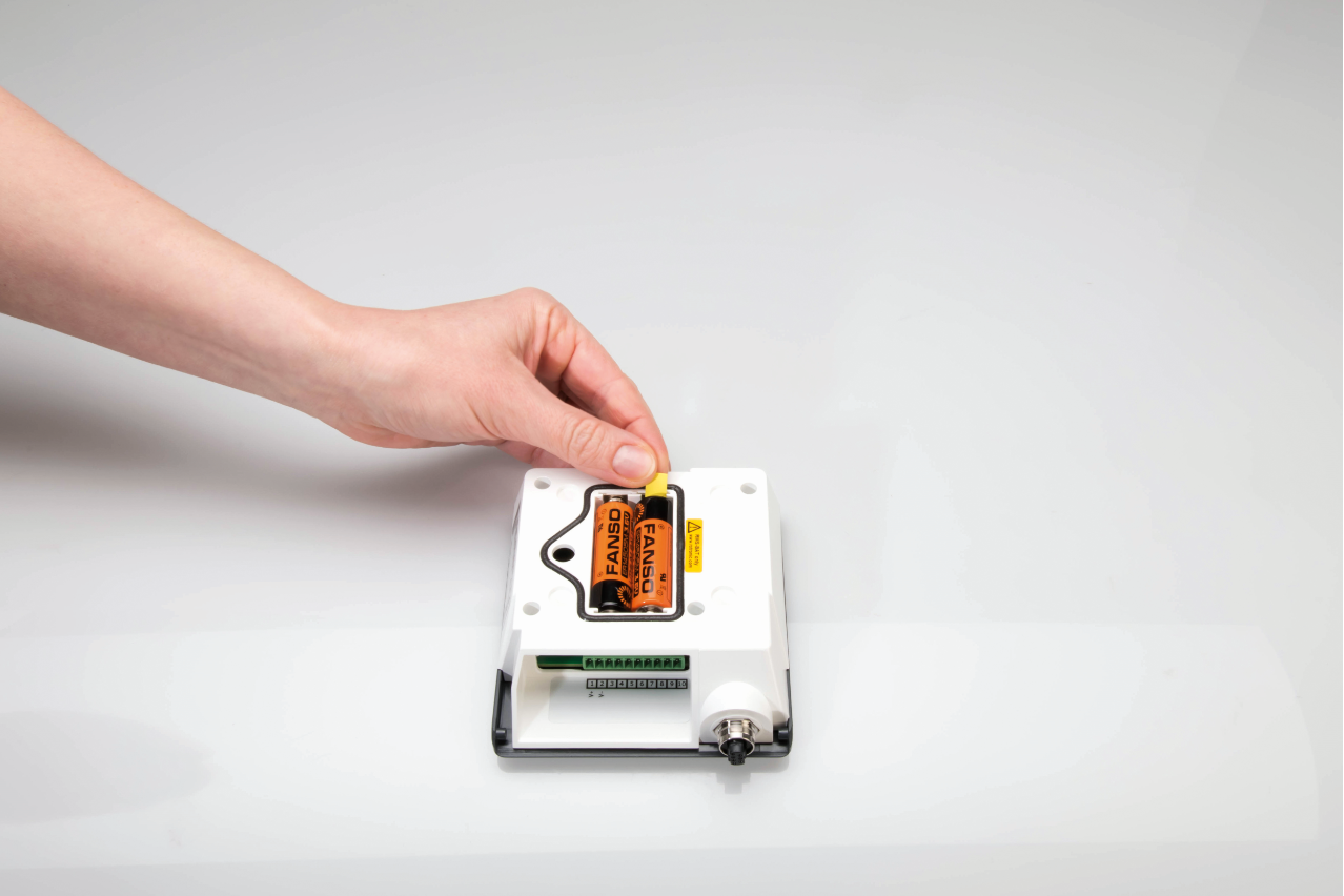
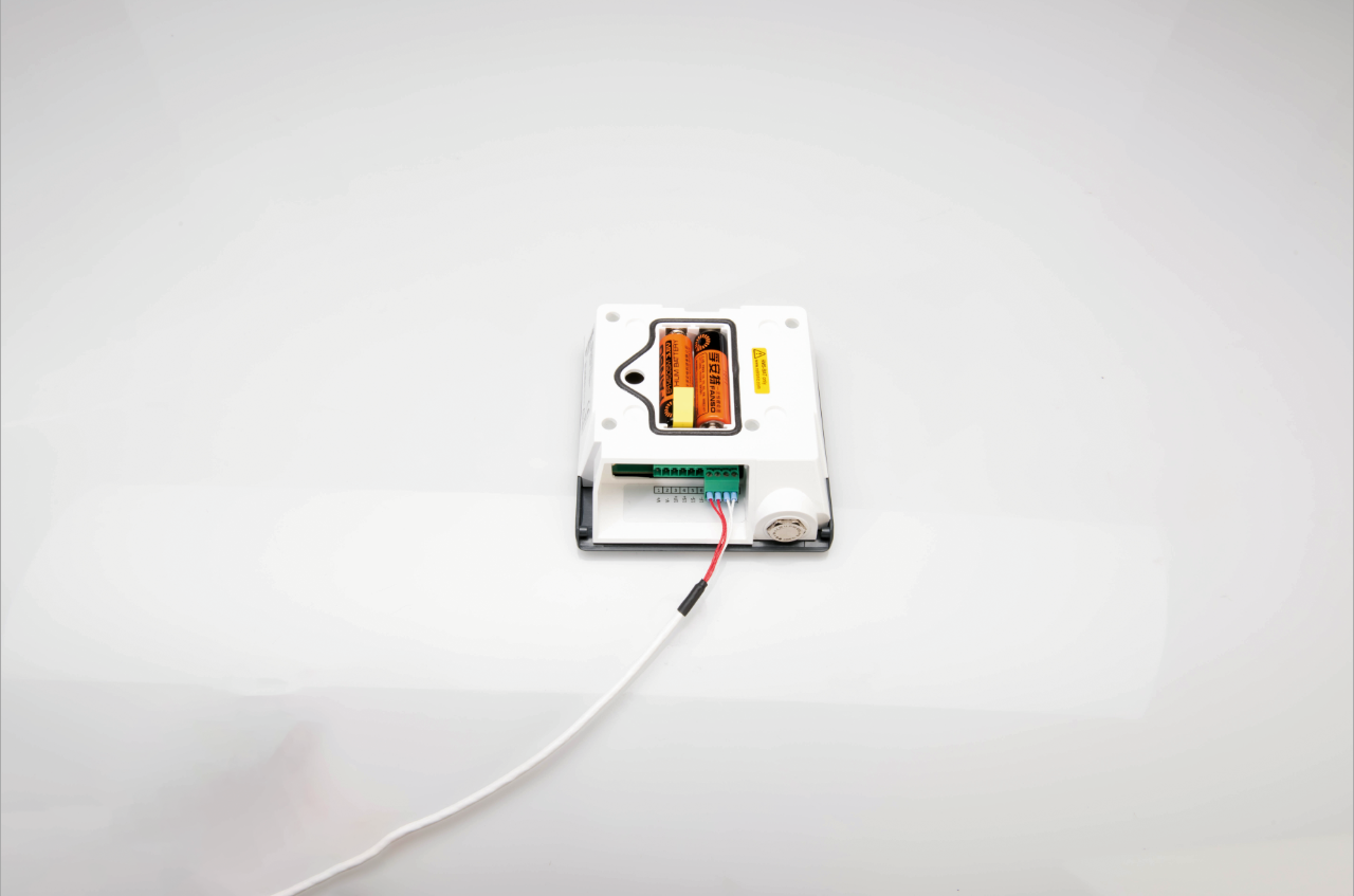
The RMS-BAT batteries should already be mounted in the module when included:
To do: Remove the yellow tag to enable the battery power. |
Step 5 |
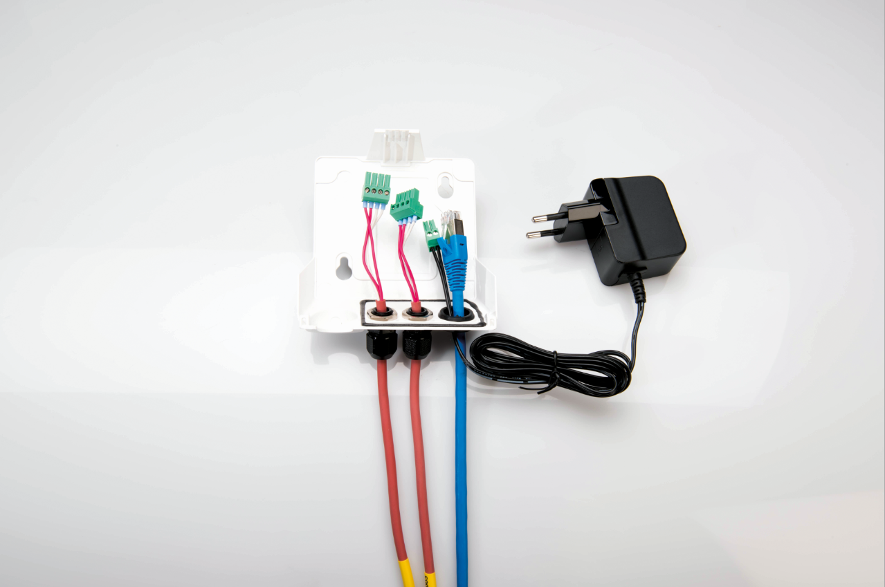
IMPORTANT: Before attaching the power supplies or measurement probes pull the necessary cables through the mounting plate with the necessary joints in place:
|
Step 6 |
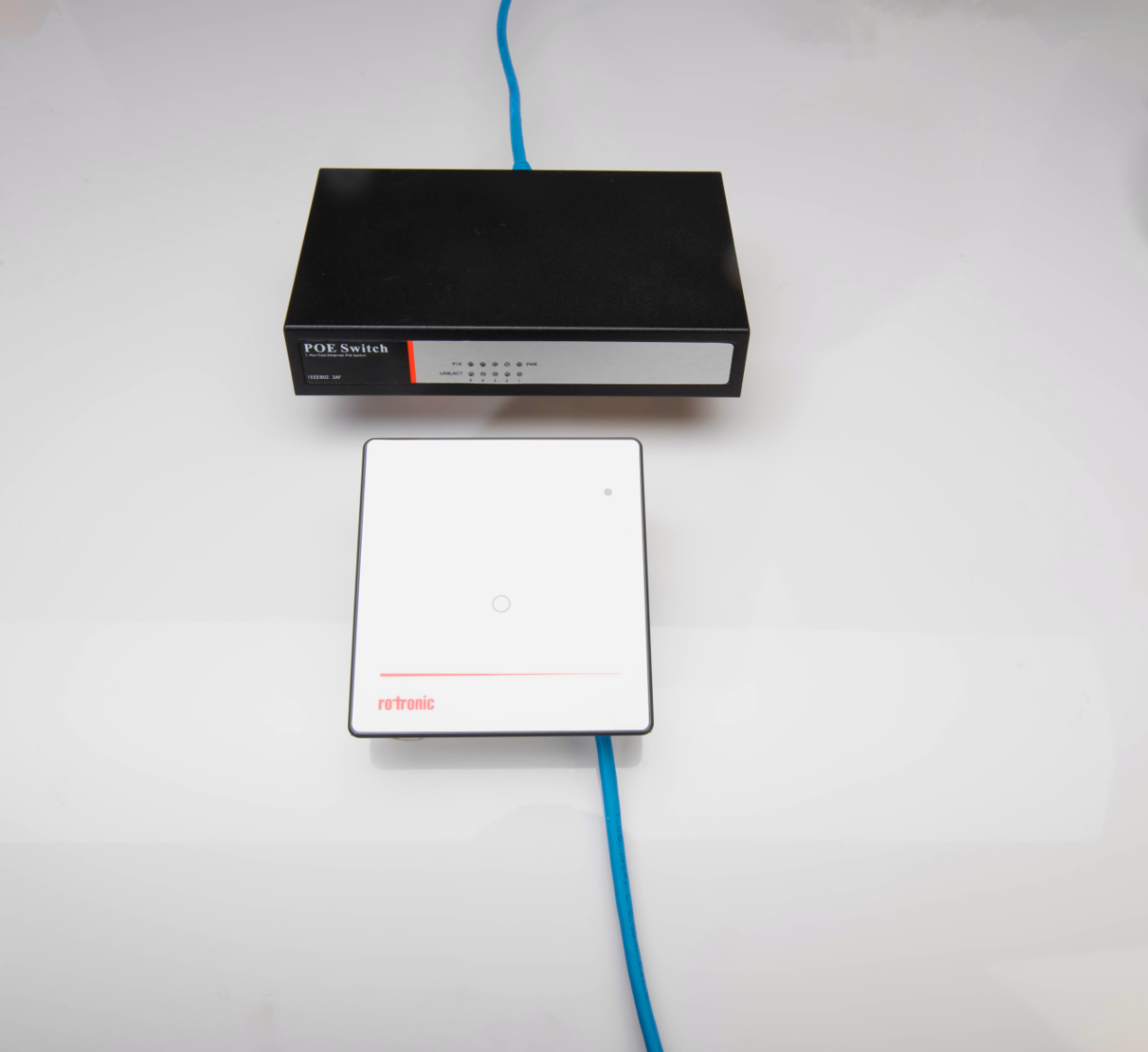
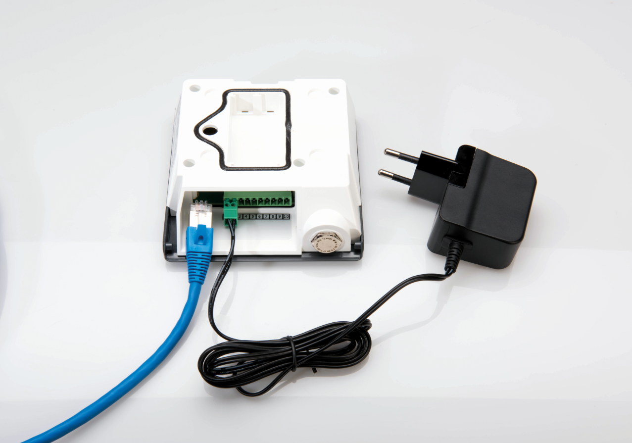
For PoE installations:
Setup: 1) Plug the RJ45 Ethernet cable into the wall mount module. 2) Plug the other end of the RJ45 Ethernet cable to the PoE switch/network. |
Step 7 |
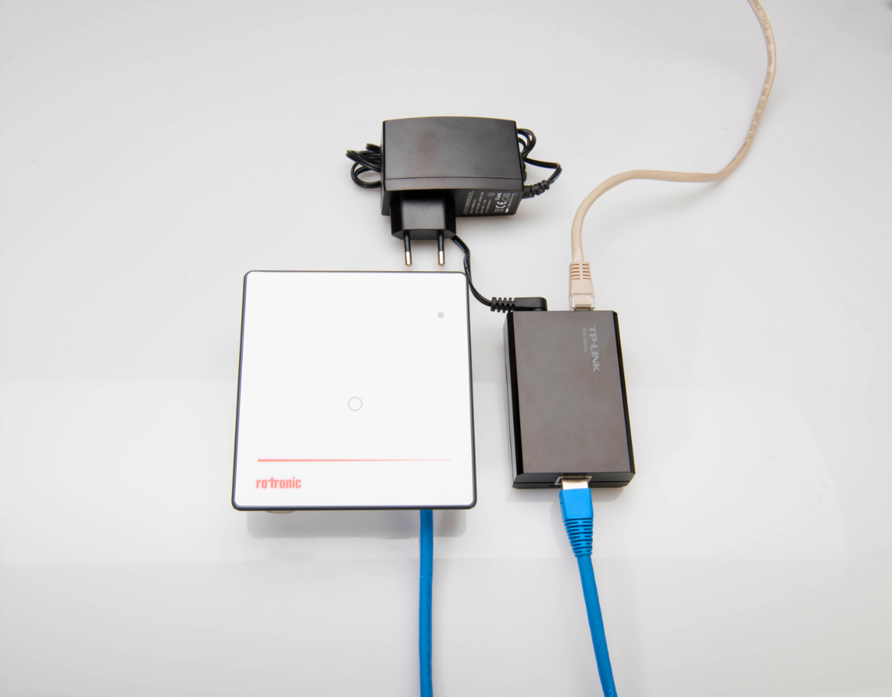
For PoE injector installations:
Setup: 1) Plug the RJ45 Ethernet cable into the PoE injector network input. 2) Plug the other end of the RJ45 Ethernet cable to the network. 3) Plug the second RJ45 Ethernet cable into the PoE injector device input. 4) Plug the other end of the second RJ45 Ethernet cable to the wall mount module. 3) Plug the power supply into the PoE injector. 4) Plug the power supply into a power source. |
Step 8 |
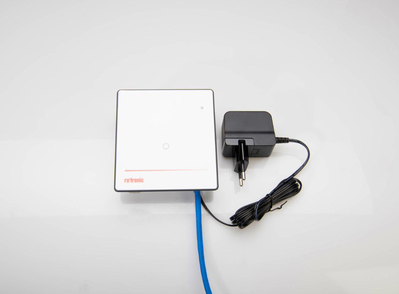
For 24VDC installations (can also be combined with a PoE network):
Setup: 1) Plug the RJ45 Ethernet cable into the wall mount module. 2) Plug the other end of the RJ45 Ethernet cable to the network. 3) Plug the power supply into the wall mount module, pins 1 and 2. 4) Plug the power supply into a power source. |
Step 9 |
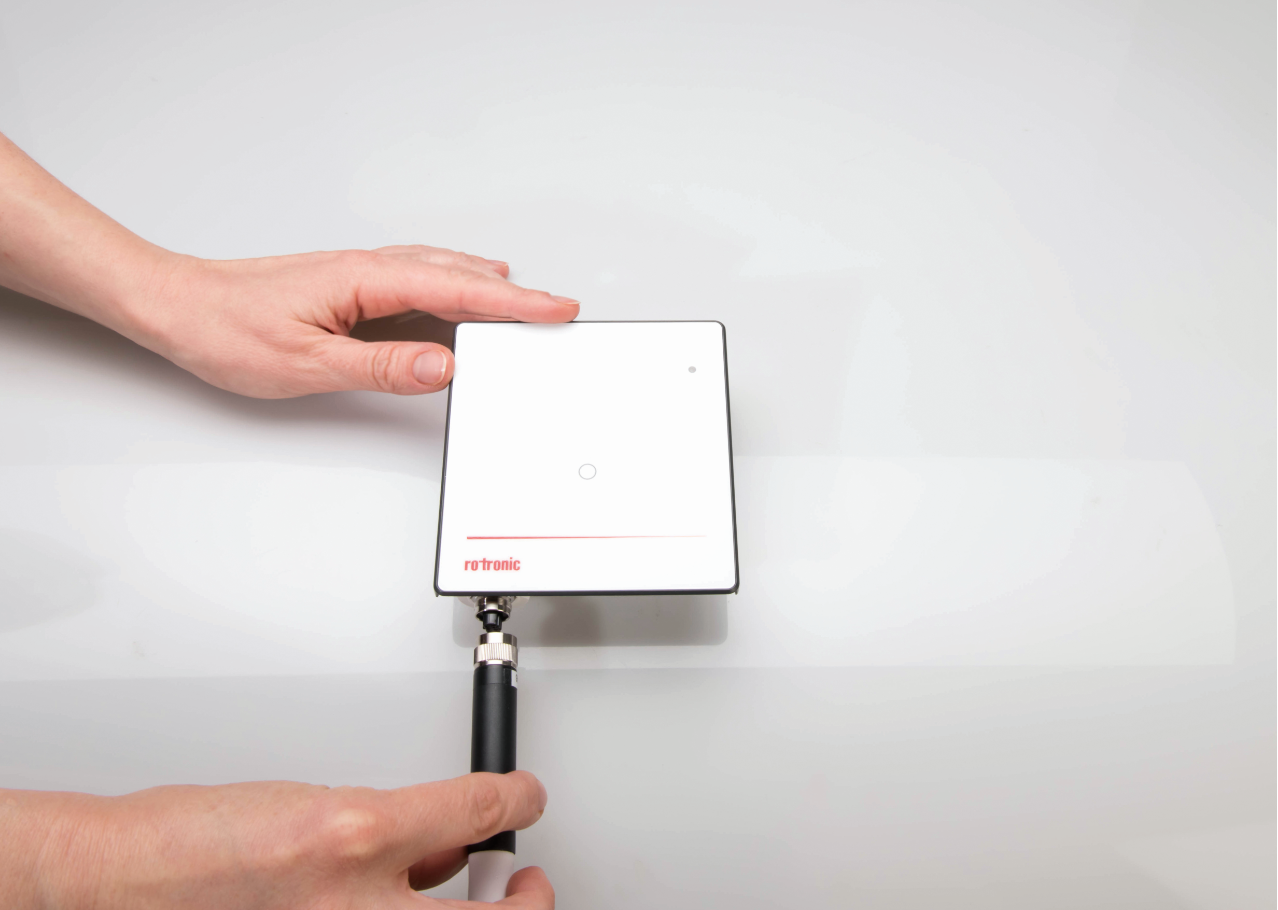
For wall mount modules (RMS-LOG-L/868/915) with digital probes (HCD, PCD, CCD):
To do: Align the connector and manually screw in the probe ensuring that the nut is tight. |
Step 10 |
For wall mount modules (RMS-LOG-T30-L/868/915) with Pt100 connectors (for T30-xxxx probes):
To do: Screw the T30 Sensor into the green connector based upon the Electrical Connections. Connect the probe to the wall mount module. |