Device description
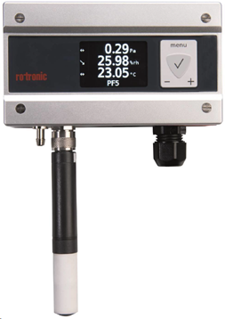
The PF4/5 is the latest generation transmitter with an integrated differential pressure sensor and 1 Pt100 or HC2 probe/analog input and 1 relay.
Important: Please consult the PF4/5 user manual as well as the HW4 manual for PF4/5 devices for further details. |
Network configuration of the device
To add the PF4/5 into the RMS, it is necessary to setup the individual network configuration of the device such as:
oDHCP active or fixed IP address
oHost name
The PF4/5 default settings are:
oDHCP on
oFixed IP address 192.168.1.1 (when DHCP is disabled)
oHost name PF45-XXXXXXXX (where XXXXXXXX represents the serial number of the device)
Important: The Digi Device Discovery Tool does not work with the PF4/5 |
The Options to get the actual device settings are:
oDevice display (if existent)
oAutomatic or manual device search function via HW4 through the Ethernet connection or by using an AC3006 or AC3009 USB service cable.
oPrompt window > ping host name
oTyping the host name into the address bar of the web browser does not work. The PF4/5 does not have a device internal Webservice.
Integration into RMS via the RMS-CONVERTER-100
Step 1 |
Log in to the RMS software. Select "Tools" > "Setup" > "Devices". Select the RMS-CONVERTER and click on "Add/Search" devices:
|
Step 2 |
Select the device type in the drop down menu.
It is possible to type the IP address or host name into the "IP address" field.
IMPORTANT: If the field stays empty, RMS will not search for the device automatically. 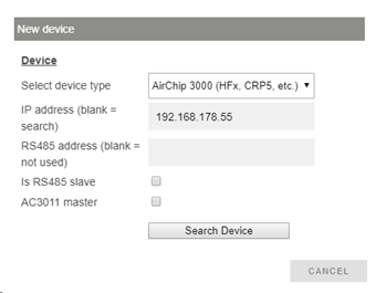
|
Step 3 |
The device appears: configure accordingly. 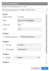 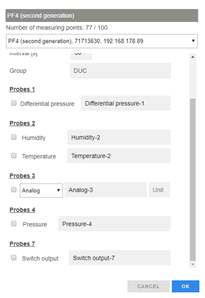
NOTE: The interval cannot be shorter than the interval of the RMS-CONVERTER-100.
IMPORTANT: If all check marks for measurement points are not set during initial installation and you wish to expand it later, then the same device needs to be added again with the same identification and IP address (there is no need to delete the device before adding it). The desired check marks can then be set. After completing this process, the added or updated measurement points will appear. |
Step 4 |
The device is added. 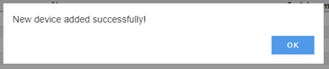
|
Step 5 |
IMPORTANT: Overwritten settings. By adding the device to RMS via the RMS-CONVERTER-100, the following configuration will be overwritten on the device: oFix value humidity: disabled oFix value temperature: disabled oFix value differential pressure: disabled oFix value calculation: disabled oFix value analog input: disabled oFix value flow: disabled oFix value ambient pressure: disabled oFix value if no probe is connected: disabled oDefault relative humidity unit: %rh oDefault temperature unit: °C oDefault pressure unit: Pa oDefault flow unit: m/s oDefault analogue input unit: empty oDefault ambient pressure unit: hPa oLink alarm on every measurement parameter to relay: disabled oRelay mute: disabled oRelay alarm on delay: disabled oRelay off after maximum time: disabled
NOTE: If one of the settings above is changed with HW4 further to the initial installation into RMS, then RMS will not note the change. However, such a change would cause RMS to not work correctly. The changes will however be overwritten should the RMS-CONVERTER-100 reboot (due to a short power interruption). |
Step 6 |
Finish configuration.
|
Functionality within RMS
Step 1 |
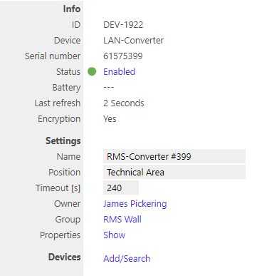
Device settings: log in to the RMS software. Select "Tools" > "Setup" > "Devices". Select the device.
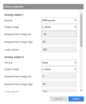
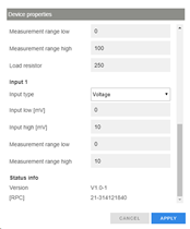
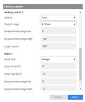
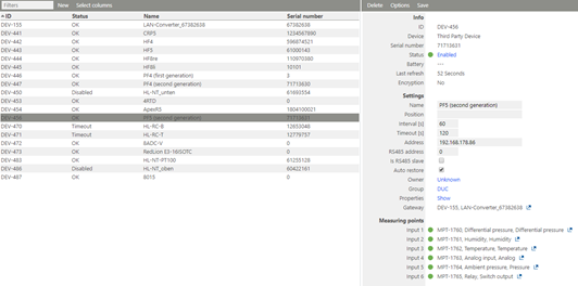 oStatus: the device can be disabled/enabled. When disabled, the RMS-CONVERTER will not send any requests. oSettings: Any settings can be changed and confirmed by clicking on "Save". oProperties: Show. The settings can be shown and configured.
IMPORTANT: Under "Options", "the firmware update", "import firmware file", "import device definition" and "device inventory" are not supported for this device.
IMPORTANT: The output range, the sources and the measurement ranges of the analog outputs 1 and 2, can be scaled and stored within the device clicking "Apply". |
|||
Step 2 |
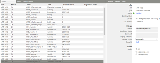
Measurement point settings: log in to the RMS software. Select "Tools" > "Setup" > "Measuring point".
Select the measuring point: oStatus: the measuring point can be disabled/enabled. oSettings: Any settings can be changed and confirmed by clicking on "Save".
|
|||
Step 3 |
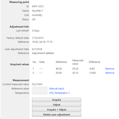
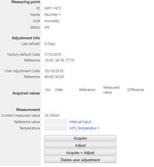
Adjustment: log in to the RMS software. Select "Tools" > "Adjustment". Select the measuring point. Click on "Refresh now".
General procedure: oType the humidity reference value and click "Acquire" oRepeat until the desired number of adjustment points are acquired. NOTE: The user of this feature must take care about sufficient stable circumstances for a data acquisition. Please take the interval into account. One value after every 60 seconds does not detect short-term changes of the value. oClick "Adjust" to finish. oUse the "Acquire + Adjust" button for one point adjustment. oClick "Delete user adjustment" to delete the last user adjustment. 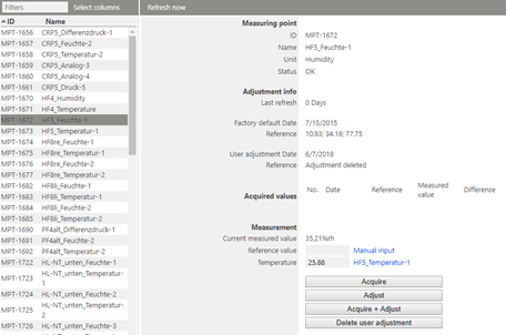
The PF4/5 has different adjustment scenarios for differential pressure.
Common adjustment The PF4/5 can be adjusted at multiple reference pressure values.
NOTE: A new common adjustment overwrites the common adjustment before, but does not overwrite the 0-point compensation.
➢0-Point compensation To compensate long term drift, a 0-Point compensation is recommended. 1.Type in "0" as the reference value and click "Acquire + Adjust" (or "Acquire" and then "Adjust") 2.A valve closes the "+" and "-" connectors of the sensor internally and defines a new 0-point. This procedure needs app. 10 sec. The PF5 will not be able to send measurement values out during this time.
NOTE: The PF4 has a 0-point compensation integrated within the device internal sensor. No extra adjustment is necessary.
NOTE: A new 0-Point compensation overwrites the previous 0-Point compensation, but doesn’t overwrites the current One point (≠0 Pa) adjustment (see below).
NOTE: The real date and reference value cannot be shown due to missing compatibility of these systems.
For relative humidity and temperature:
NOTE: For humidity, multiple points can be acquired and adjusted. For temperature, 1 or 2 points. |
|||
Step 4 |
Data logging: the PF4/5 has no internal memory, the PF4/5 is not battery powered. So the PF4/5 cannot log during a power interruption.
In case of a communication interruption to the RMS Server, the RMS-CONVERTER-100 logs the data of the PF4/5. After the interruption, RMS requests the data from the RMS-CONVERTER-100.
In case of a communication interruption between the RMS-CONVERTER-100 and the PF4/5, the PF4/5 would not log the data. |
|||
Step 5 |
Sensor error: In case of one sensor error out of the two, RMS displays a sensor error for both measurement values.
  |
|||
Step 6 |
Measurement alarm: Alarms linked to the measurement limits and programmed within the HC2 will not be transmitted to RMS. However if the device has a display and the display is configured correctly, the alarm will show on the display. |
|||
Step 7 |
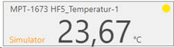
Fix values on the HC2: fixed measurement values programmed within the HC2 are displayed as simulators within RMS.

IMPORTANT: In case of an active fix value of one measurement value of a HC2, RMS will show "simulator connected" for both measurement values of the probe. |