•Drilling Template Wall Bracket
The following instructions describe installation of the data logger step by step.
Step 1 |
Press a blunt object (e.g. screwdriver in the AC1321 mounting kit) lightly into the hole opening on the top side of the housing. The flap springs open. 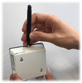 |
Step 2 |
Press the cover to the back and take off from the basic unit. 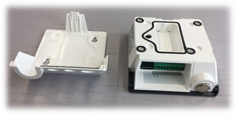 |
Step 3 |
The cover has two suspension openings and two additional prepared fastening possibilities1. 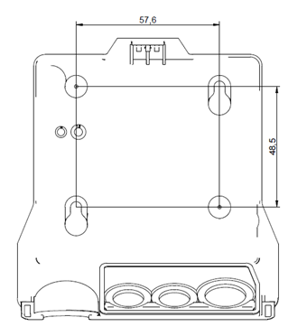 |
Step 4 |
Make a round opening in the large rubber seal (use the mounting cone in AC1321), pass the cable through it and fit the rubber plug in the cover. 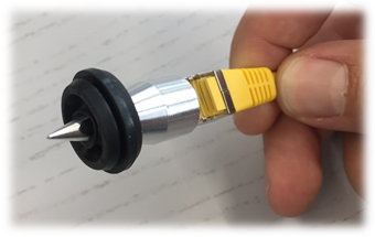 |
Step 5 |
Plug the cable into the device2. For secure fastening and to ensure a reliable data link, make sure it clicks in audibly. 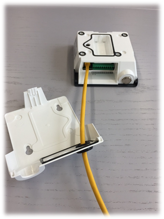 |
Step 6 |
If necessary, connect the device to a power supply.
For T30: Connect the PT100 probes 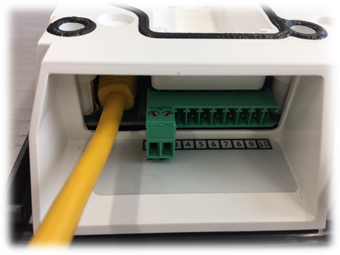 |
Step 7 |
The wall bracket is fastened to the wall with screws according to the drilling template. The screws may only protrude so far that the device can click into place properly when put on to the fastened cover.3 4 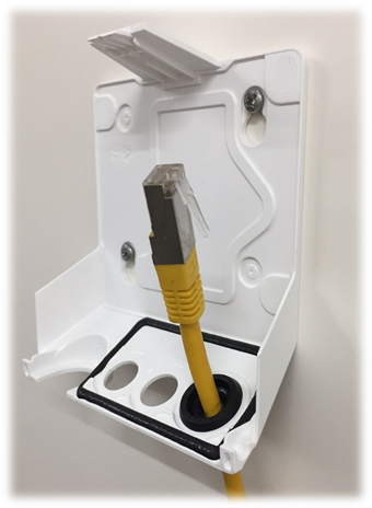 |
Step 8 |
The housing is put in the wall bracket and clicked into place. 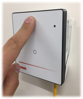 |
Step 9 |
Insert the probe and fasten with the thumb screw. 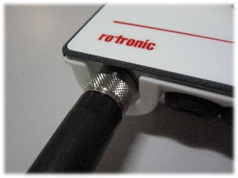 |
1 Only the mounting points provided should be used for mounting.
2 The connected cable may not exceed a length of 30 m at most. Disruptions can occur in operation if a longer cable is used.
3 The screws must not be tightened.
4 Only use the screws provided in the package. Screw specifications: M3.5. head strength 2.5 mm, head diameter 7 mm