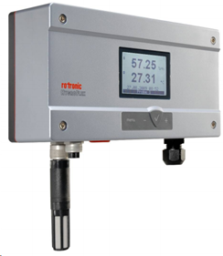
Device description
The HF8 is a transmitter with 2 HC2 or 2 analog inputs and 4 relays.
The HF8 transmitters are also dataloggers. The units with display will always indicate the time in the coordinated universal time and not the local time. All data visualised within the RMS software will be indicated in the local time.
Important: Please consult the HF8 user manual as well as the HW4 manual for HF8 devices for further details. |
Network configuration of the device
To add the HF8 into the RMS, it is necessary to setup the individual network configuration of the device such as:
oDHCP active or fixed IP address
oHost name
The HF8 default settings are:
oFixed IP address 192.168.1.1
oHost name not defined
To find and configure the network settings of the device, please connect the device into the LAN and use the Digi Device Discovery Tool (https://www.rotronic.com/de-ch/rms/downloads-rms?form_key=usHTRE667OOcxi1J&download_type=Drivers+and+tools).
Step 1 |
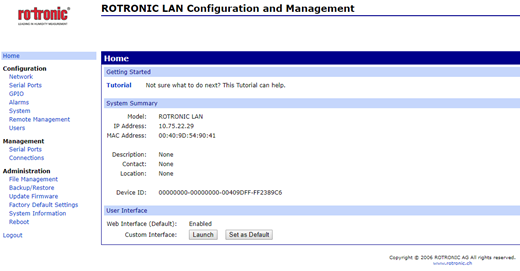
➢Discover the IP address: Open and execute DigiDeviceDiscovery.exe. The device search starts automatically. Double click on the device: a web browser opens.
➢If the IP address or the host name device is known, please type into the address bar of the web browser: http://ipaddress (e.g. http://192.178.1.1) or http://hostname (e.g. http://SN12345678). |
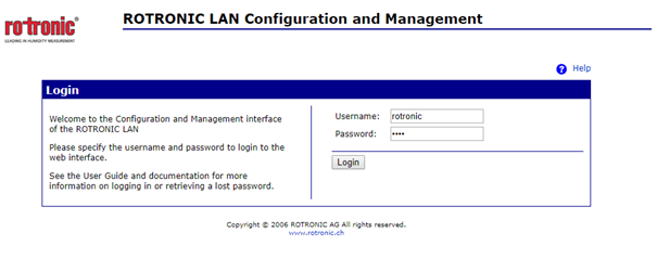
Step 2 |
Log in for further network configuration: oDefault user: rotronic oDefault password: wlan
|
Step 3 |
Check or change the network settings:
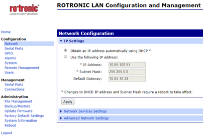
IMPORTANT: Rotronic recommends using a fixed IP address for the RMS-CONVERTER-100 as well as for the digital devices. The reason being the support of the log function within the RMS-CONVERTER-100 in case of any interruption to the RMS server. |
Step 4 |
Check or change the host name and set the check mark for "Enable AutoIP address assignment":
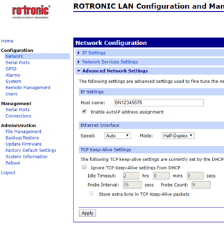 If a DNS is active within the network, the RMS / RMS-CONVERTER-100 can communicate based on the host name instead of the IP address. |
Step 5 |
Disable the Discovery mode:
The device search function of HW4 and the Discovery tool uses a Device Discovery function (ADDP). At the end of the configuration, it is meaningful to disable this feature. o"Network" > "Network Services Settings" > remove the check mark of "Enable Device Discovery (ADDP)".
IMPORTANT: Parallel and unwished communication due to the opening of HW4 will be avoided. A side effect is, that this device will not automatically be found by HW4 or the Discovery tool anymore. To access the device via HW4, the IP address must be added manually. |
Step 6 |
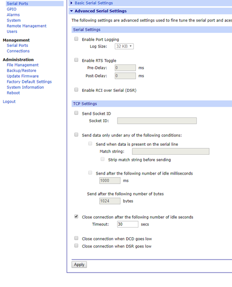
Close connection after the following number of idle seconds:
Unwished parallel communication/requests to the Ethernet address of the Rotronic device can cause an unwished blocking of the device's internal access to the Ethernet port. For that reason the following setting can be done: o"Serial Ports" > "Advanced serial settings" > "TCP Settings" > set a check mark to "Close connection after the following number of idle seconds". o> "Serial Ports" > "Advanced serial settings" > "TCP Settings" > "Timeout: xx seconds".
If the port is blocked then the device will renew/unblock the port by itself after the chosen timeout.
This way a permanent timeout of the device will be avoided. The loss of data will be reduced significantly. For an RMS-CONVERTER-100 interval of 60 seconds, a timeout of 10 to 30 seconds would be meaningful.
 |
Integration into RMS via the RMS-CONVERTER-100
Step 1 |
Log in to the RMS software. Select "Tools" > "Setup" > "Devices". Select the RMS-CONVERTER-100 and click on "Add/Search" devices:
 |
||
Step 2 |
Select the device type in the drop down menu.
It is possible to type the IP address or host name into the "IP address" field.
IMPORTANT: If the field stays empty, RMS searches automatically. If the automatic search function is disabled, an IP address or a host name has to be typed into the field. 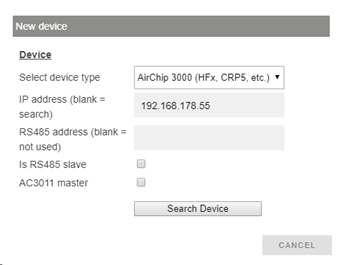 |
||
Step 3 |
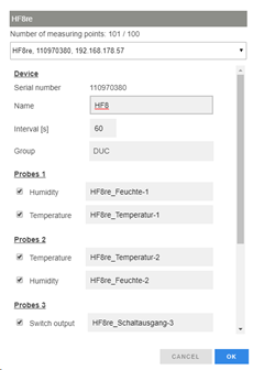
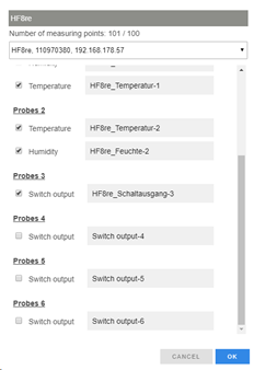
The device appears: configure accordingly.
NOTE: The interval cannot be shorter than the interval of the RMS-CONVERTER-100.
IMPORTANT: If all check marks for measurement points are not set during initial installation and you wish to expand it later, then the same device needs to be added again with the same identification and IP address (there is no need to delete the device before adding it). The desired check marks can then be set. After completing this process, the added or updated measurement points will appear. |
||
Step 4 |
The device is added. 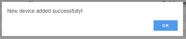 |
||
Step 5 |
IMPORTANT: Overwritten settings. By adding the device to RMS via the RMS-CONVERTER-100, the following configuration will be overwritten on the device: oFix value humidity: disabled oFix value temperature: disabled oFix value if no probe is connected: disabled oDefault relative humidity unit: %rh oDefault temperature unit: °C oLink alarm on humidity to relay: disabled oLink alarm on temperature to relay: disabled oLink alarm on calculated value to relay: disabled
NOTE: If one of the settings above is changed with HW4 further to the initial installation into RMS, then RMS will not note the change. However, such a change would cause RMS to not work correctly. The changes will however be overwritten should the RMS-CONVERTER-100 reboot (due to a short power interrupt). |
||
Step 6 |
Finish configuration. |
Functionality within RMS
Step 1 |
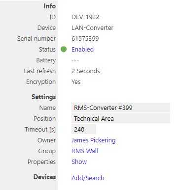
Device settings: log in to the RMS software. Select "Tools" > "Setup" > "Devices". Select the device.
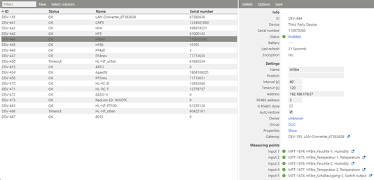
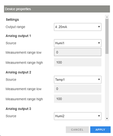
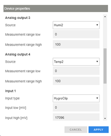
oStatus: the device can be disabled/enabled. When disabled, the RMS-CONVERTER-100 will not send any requests. oSettings: Any settings can be changed and confirmed by clicking on "Save". oProperties: Show. The settings can be shown and configured.
IMPORTANT: Under "Options", "the firmware update", "import firmware file", "import device definition" and "device inventory" are not supported for this device.
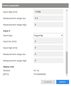
IMPORTANT: The output range, the sources and the measurement ranges of the analog outputs 1 and 2, can be scaled and stored within the device clicking "Apply". |
||
Step 2 |
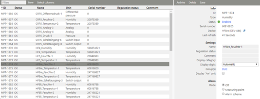
Measurement point settings: log in to the RMS software. Select "Tools" > "Setup" > "Measuring point".
Select the measuring point: oStatus: the measuring point can be disabled/enabled. oSettings: Any settings can be changed and confirmed by clicking on "Save".
|
||
Step 3 |
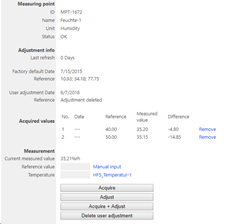
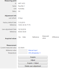
Adjustment: log in to the RMS software. Select "Tools" > "Adjustment". Select the measuring point. Click on "Refresh now".
General procedure: oType the humidity reference value and click "Acquire" oRepeat until the desired number of adjustment points are acquired. NOTE: The user of this feature must take care about sufficient stable circumstances for a data acquisition. Please take the interval into account. One value after every 60 seconds does not detect short-term changes of the value. oClick "Adjust" to finish. oUse the "Acquire + Adjust" button for one point adjustment. oClick "Delete user adjustment" to delete the last user adjustment.
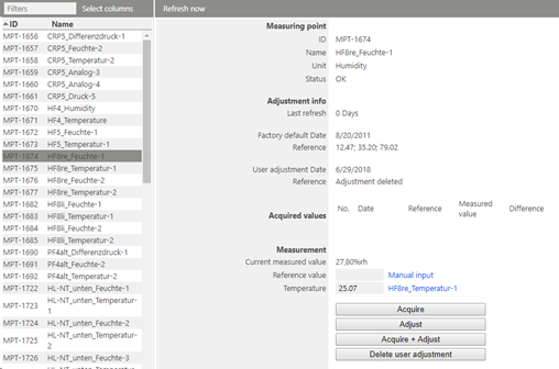
NOTE: For humidity, multiple points can be acquired and adjusted. For temperature, only 1 or 2 points. |
||
Step 4 |
Data logging: the HF8 has an internal memory, the HF8 is not battery powered. So the HF8 cannot log during a power interruption.
In case of a communication interruption to the RMS Server, the RMS-CONVERTER-100 logs the data of the HF8. After the interruption, RMS requests the data from the RMS-CONVERTER-100.
In case of a communication interruption between the RMS-CONVERTER-100 and the HF8, the HF8 would log the data. After the interruption, RMS requests the data from the RMS-CONVERTER-100.
The HF8 can log up to 10,000 relative humidity and temperature values provided by a single HygroClip 2 probe or up to 20,000 data values provided by a single 1-channel analog probe. Both probe inputs can be logged at the same time and in that case the recording capacity per probe is cut in half. The calculated parameter cannot be recorded. With an interval of 60 s, the HF8 is able to bridge a communication interruption of maximum: o10’000 min ≈ 167 h ≈ 7 d > 1 HygroClip connected or o5’000 min ≈ 83 h ≈ 3.5 d > 2 HygroClip connected or o20’000 min ≈ 333 h ≈ 14 d > 1 Analog input used.
This time can be increased by using a higher log interval.
|
||
Step 5 |
Sensor error: In case of one sensor error out of the two, RMS displays a sensor error for both measurement values.
  |
||
Step 6 |
Measurement alarm: Alarms linked to the measurement limits and programmed within the HC2 will not be transmitted to RMS. However if the device has a display and the display is configured correctly, the alarm will show on the display. |
||
Step 7 |
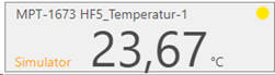
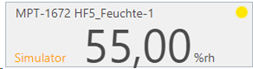
Fix values on the HC2: fixed measurement values programmed within the HC2 are displayed as simulators within RMS.

IMPORTANT: In case of an active fix value of one measurement value of a HC2, RMS will show "Simulator connected" for both measurement values of the probe. |