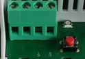
Connection of external power supply
Marking |
Function |
 |
|---|---|---|
V+ |
Power Supply + |
|
V- |
Power Supply - |
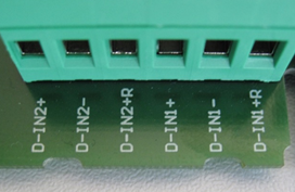
Connection of digital inputs
Marking |
Function |
 |
|---|---|---|
D-IN1+R |
Input 1 Reed/Gate |
|
D-IN1- |
Input 1 GND |
|
D-IN1+ |
Input 1 Voltage Input |
|
D-IN2+R |
Input 2 Reed /Gate |
|
D-IN2- |
Input 2 GND |
|
D-IN2+ |
Input 2 Voltage Input |
Connection with Voltage Input or Reed/Gate
D-IN1+ |
D-IN1- |
D-IN1+R |
D-IN2+ |
D-IN2- |
D-IN2+R |
|
|---|---|---|---|---|---|---|
IN1 Reed |
contact- |
contact + |
||||
IN1 Input |
5…24 V |
GND |
||||
IN2 Reed |
contact - |
contact + |
||||
IN2 Input |
5…24 V |
GND |
Configure the hardware to switch between Voltage Input or Reed/Gate
There are 2 options for inputs, that need to be configured within the system (the two digital inputs can be configured independently):
•Logical voltage level: The user has the possibility to use the input with 5 ... 24 VDC as the high level of the digital input.
•Reed/Gate: The user has the possibility to connect the inputs and use them as gate (e.g. with a relay).
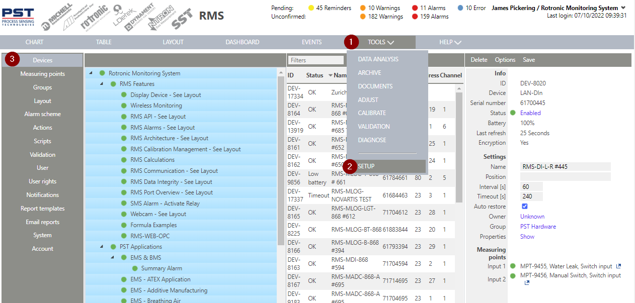
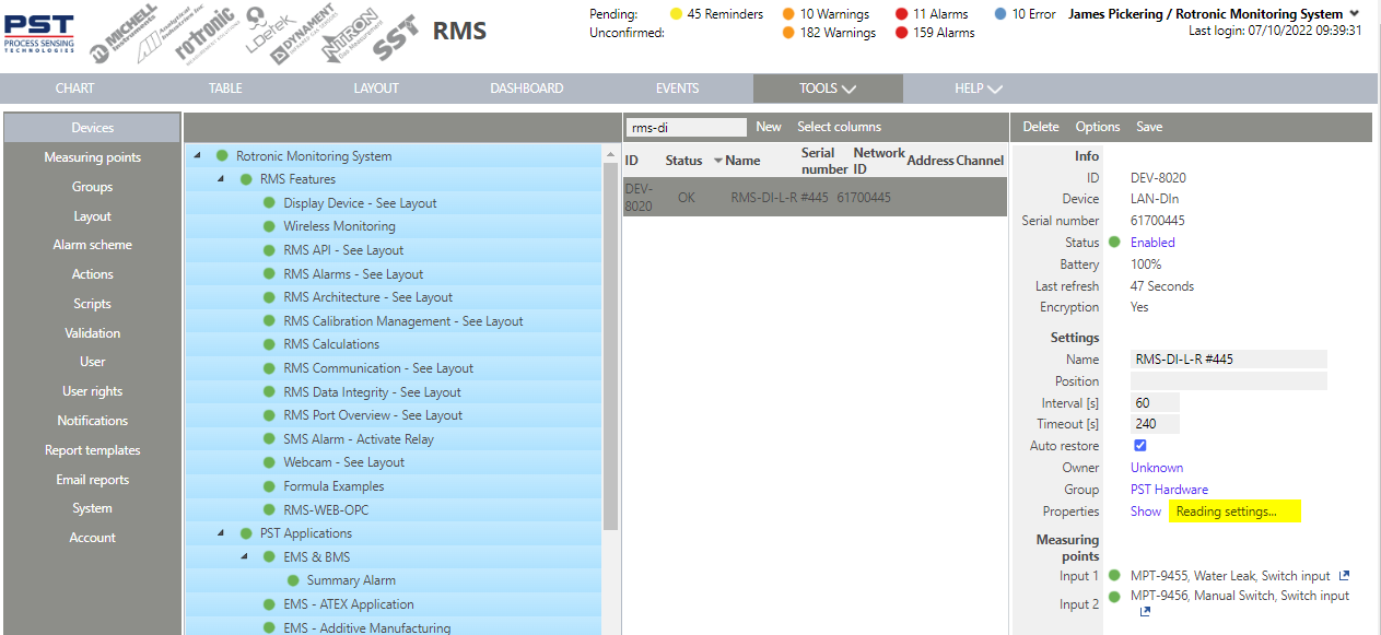
Configure the hardware via the RMS software
Step 1 |
Select Tools>Setup>Devices:
|
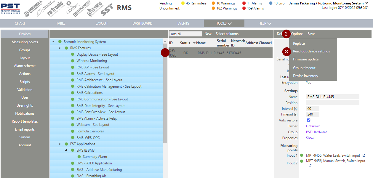
Step 2 |
Select the RMS-DI device, click on options and read out device settings:
|
Step 3 |
Wait until the device setting have been read out and the information reading settings... disappears:
|
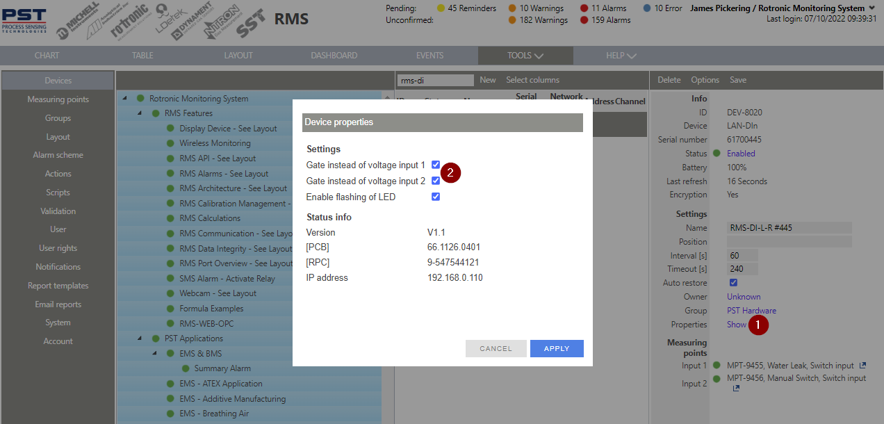
Step 4 |
Click on show properties, and update the settings. The tick box means that a Reed/Gate is being used instead of a voltage input:
|
Behavior of the inputs
The measurement of the digital inputs are event-based, which means that the device transmits data to the server only when a voltage level change is detected or the web service requests it at the fixed interval.
•If the inputs are frequently changing, the maximum allowed switching frequency is 0.833 Hz, or a change can be detected every 1.2 s.
•The inputs are independent, always active and register changes via the trigger. The device is not suitable for pulses shorter than 1.2 s.
•For the detection of the single pulses, the pulse must be at least 100 ms long. The transfer to the web service takes place with 2 different time stamps (1 s offset).
Since, especially when using low voltages such as Reed, the input cable length shall be taken into account (refer to the technical data).
Behavior in battery operation
The batteries serve to supply the device with power in the event of a failure in the external power supply. The functionality of the device is restricted in battery mode. The device continues to measure and records all data in the internal memory. The device cannot communicate via the Ethernet interface.
Lithium batteries of the type AA with 3.6 V are used, please only use RMS-BAT batteries. The poles are marked on the battery and in the battery compartment.