Under "Devices", it is possible to see the various devices within the various groups.

Figure 1: Overview of the device selection
With "Shift" or with "Ctrl", it is possible to select one or more of the devices.
With one device selected, it is then possible to replace it, read out device settings, carry out a firmware update (by before importing a firmware file).
With more than one device selected, it is then possible to read out device settings, carry out a firmware update (all selected devices must be the same).
Within the "Device settings" table, it is possible to view the following columns:
oID oStatus oDevice oName oSerial number oPosition oOwner oNetwork ID oAddress oChannel |
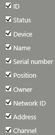 |
Figure 2: Overview of the "device settings" table
An RMS device has the following properties and setting possibilities:
Property |
Description |
|---|---|
Info |
|
Device ID |
Unique ID for the device (DEV-xx) |
Device type |
Device type (e.g. LAN logger / RH logger) |
Serial number |
Serial number of the device |
Status |
oEnabled (green status indicator) Device is enabled in the system. oDisabled (black status indicator) The system does not receive any data from the device and alarms are also not triggered. In this mode, the device is not write-protected and can be set with the RMS-Configurator. |
Battery1 |
Current battery status |
Last refresh |
Time that has passed since the system last received data from the device |
Settings |
|
Device name |
Freely selectable name |
Position |
Freely selectable description of the physical position of the device |
Interval |
Time interval for measurement and transmission of the data |
Timeout |
Time span after which an alarm is triggered if the device no longer sends data |
Auto restore |
Automatic reading out of the logger’s internal memory when an interruption in the measurements in the system’s database is established |
Owner |
User who is responsible for the device2 |
Group |
The group to which the device belongs |
Properties |
The properties are specific settings that are saved into the device: oIP address (if LAN device) oFirmware version oLED flash interval oNTC settings (only loggers with NTC connection) |
Measuring points |
|
Input3 |
Measuring point(s) of the device |
Wireless settings |
|
Address |
Radio address of the device: oGateway: fixed at 254 oRadio device: can be selected between 1…60. |
Network ID |
1…254 Networks can be defined. Per network, 1 Gateway and 60 loggers. In total 15'240 loggers can be used. |
Channel |
1…5 Channels can be defined. Per channel, 1 gateway and 60 loggers. The channel is automatically taken from the gateway that the device is paired to. |
Gateway |
A link to gateway that the device is paired to. |
1 Only input modules have a battery.
2 This function is of an informative nature only. No link with user rights.
3 A device can have one or two inputs.
The following functions are available for editing devices:
Function |
Description |
|---|---|
New |
Add new device |
Delete |
Delete device4 The measuring points of the device and all recorded data will be deleted! It is possible via system setting to require entering a text when deleting device to prevent accidental deletion.
NOTE: After deleting a wireless device, user shall press the button on the device for longer than 5 seconds to unpair it. Otherwise the device will continue sending message with original frequency, and could disturb the channel. |
Options |
Replace The device is replaced. The measuring points and settings of the device are taken over automatically. LAN devices can be replaced if the new device is not already used in the system. Gateways can always be replaced. Wireless devices can be replaced by pairing a new device. RMS-Converter can be replaced if the new converter has no monitored devices. The new converter must first be paired into the system. RMS-Converter devices can be replaced by entering new address settings (IP address, RS485 address). As soon as the converter can communicate with the new device and sends the data to the RMS, the new serial number is adopted by the system.
IMPORTANT: When using the "Replace" function, please ensure that the replacing probe is not already in the system. If the replacing probe is already in the system, it will be deleted along with the history of the probe. |
Read out device settings Read out device properties as shown in the above table. |
|
Firmware update Update the device firmware. If more than one of the same devices are selected, then a new firmware can be uploaded to all devices at once.
IMPORTANT: Only one type of firmware update can run at the time.
The update for wireless loggers can last up to 4 hours if there are 60 units connected to a gateway (4 minutes per device). If there are various firmware versions available, the device will always take the newest version. |
|
Import firmware file Import a .bin firmware file for the devices. The file will automatically be saved under "Documents" and will automatically be used for the firmware update option stated above. |
|
Import device definition Import a file to define the device properties. This option is only available for RMS web version, and can be used after a firmware update containing change in device properties. The loaded file will be stored in the database. |
|
Group timeout Settings for the group timeout function. Details see the functional specification. |
|
Device inventory Option to create a csv report about devices in selected groups and a summary. |
|
Save |
Save device settings |
4 Alarms relating to this device are ended automatically and labels deleted from the "Layout" view.