
Measure Solar Radiation in RMS
Hi RMS Community,
at the Rotronic location in Bassersdorf we have an experimental wether station that we implemented into the RMS.
Today I would like to show you how to integrate a very simple solar radiation measurement.
It could be used to detect any solar influence for climate measurements as temperature, humidity or for electrical measurements as power or efficiency of a photovoltaic system.
A very accurate but also expensive sensor would be a pyranometer.
An economic alternativ is a Silicon Solar Cell.
Measurement principle
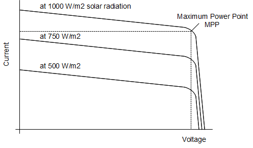
A solar cell supplies a current that depends on the solar radiation lineary.
To measure the current, a ohmic load is to be connected to the solar cell. Now the voltage over the load is to be measured as a rate of the solar radiation.
Voltage-Current-Diagram of a silicon solar cell
Setup
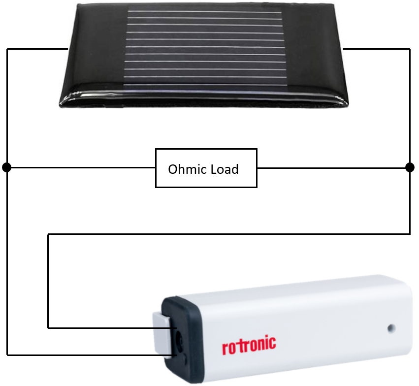
The setup is pretty simple, an ohmic resistor and a MiniLogger with a standard ADC interface of 0-10V (RMS-MADC-868-V) is to be used.
Circuit diagram of the setup
How to rate the ohmic load?
Looking into the data sheet of the solar cell there are two electric variables:
The next diagram shows, how to interpret
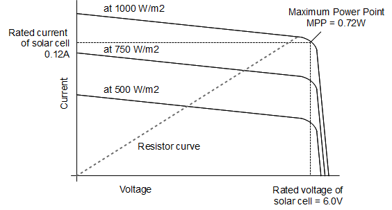
The resistance of the load at the maximum power point MPP is 6.0V / 0.12V = 50Ohm.
The next standadized resistance would be 56Ohm.
The voltage over the load is
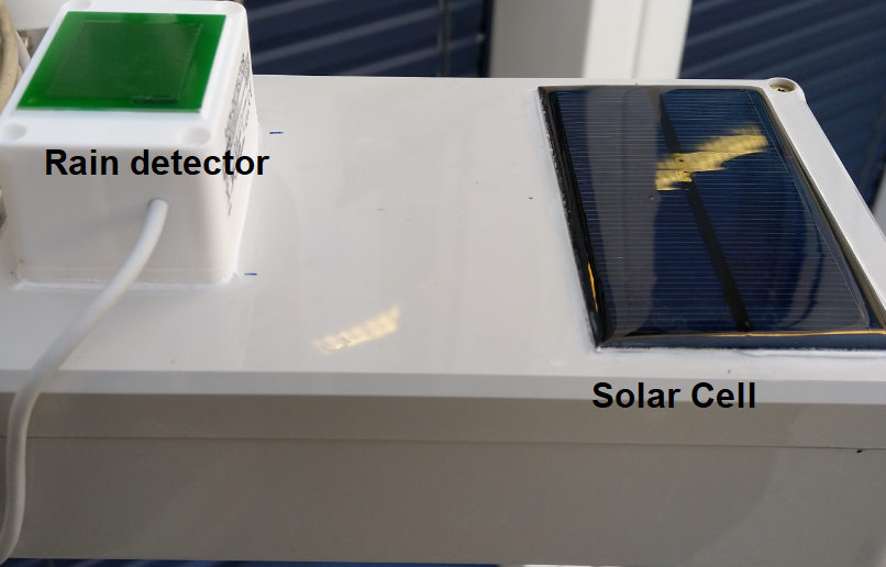
Experimental setup
Input scale of the MiniLogger
Please click on Tools -> Setup -> Devices -> Choose the MiniLogger -> Click on Show Properties:
How accurate is this measurement?
There are some influences on the measurement as:
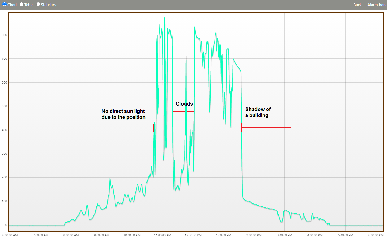
Diagram of the solar radiation over 12 hours
at the Rotronic location in Bassersdorf we have an experimental wether station that we implemented into the RMS.
Today I would like to show you how to integrate a very simple solar radiation measurement.
It could be used to detect any solar influence for climate measurements as temperature, humidity or for electrical measurements as power or efficiency of a photovoltaic system.
A very accurate but also expensive sensor would be a pyranometer.
An economic alternativ is a Silicon Solar Cell.
Measurement principle
A solar cell supplies a current that depends on the solar radiation lineary.
To measure the current, a ohmic load is to be connected to the solar cell. Now the voltage over the load is to be measured as a rate of the solar radiation.
Voltage-Current-Diagram of a silicon solar cell
Setup
The setup is pretty simple, an ohmic resistor and a MiniLogger with a standard ADC interface of 0-10V (RMS-MADC-868-V) is to be used.
Circuit diagram of the setup
How to rate the ohmic load?
Looking into the data sheet of the solar cell there are two electric variables:
- Rated voltage = 6.0V
- Rated current = 0.12A
The next diagram shows, how to interpret
The resistance of the load at the maximum power point MPP is 6.0V / 0.12V = 50Ohm.
The next standadized resistance would be 56Ohm.
The voltage over the load is
- app. 5.6V at 1000W/m2 solar radiation
- app. 2.8V at 500W/m2 solar radiation and so on.
Experimental setup
Input scale of the MiniLogger
Please click on Tools -> Setup -> Devices -> Choose the MiniLogger -> Click on Show Properties:
- The Measurement range low should be set to 0 (0W solar radiation at night).
- The Measurement range high should be set to the radiation power expected at a signal of 10V. As the setup never supplies a voltage much higher than 5.6V, the theoretical max. scaling might be caluclated: (1000W/5.6V)*10V=1786W.
How accurate is this measurement?
There are some influences on the measurement as:
- Temperature -> small influence on the voltage
- Variation of Air Mass (AM) -> a rate represents the earth athmosphere homoginious dlyistributed (for solar cells only in laboratory reproducable)
- Frequency sprectrum of the sun light -> Silicon detects only a part of the sun light spectrum. CO2 or H2O in the athmosphere e. g. can influence solar radation landing on the earth surface at higher frequencies. These influences cannot be measured by silicon.
- Voltage over the load -> The load might be chosen higher than 50Ohm in the example above to detect the linear light dependency of the current. If the load or the current differes from datasheet for several further reason, than you have further influences on the measurement.
- Dust and polution on the solar cell surface over the time.
Diagram of the solar radiation over 12 hours
No matching content in this article.